
A method and system for realizing intelligent switching of dual GPS antennas

A GPS antenna and intelligent switching technology, applied in radio wave measurement system, satellite radio beacon positioning system, measuring device, etc., can solve the problems of narrow positioning angle range and inability to meet all-round GPS positioning

Inactive Publication Date: 2018-01-02
SHENZHEN PROTRULY ELECTRONICS CO LTD
View PDF5 Cites 3 Cited by
  • Summary
  • Abstract
  • Description
  • Claims
  • Application Information

AI Technical Summary

Problems solved by technology

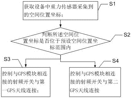
[0005] In view of the deficiencies in the above-mentioned prior art, the purpose of the present invention is to provide users with a method for realizing intelligent switching of dual GPS antennas and its system, so as to overcome the narrow angle range of GPS positioning equipment in the prior art and cannot satisfy all requirements. Flaws in azimuth GPS positioning

Method used


Image

  • A method and system for realizing intelligent switching of dual GPS antennas
  • A method and system for realizing intelligent switching of dual GPS antennas
  • A method and system for realizing intelligent switching of dual GPS antennas

Examples


Embodiment Construction

[0041] In order to make the objectives, technical solutions and advantages of the present invention clearer and clearer, the present invention will be further described in detail below with reference to the accompanying drawings and embodiments. It should be understood that the specific embodiments described here are only used to explain the present invention, but not to limit the present invention.

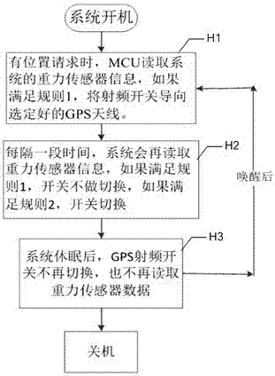
[0042] Due to the strong directivity of the antenna, and under normal circumstances, it is facing upwards to get good gain, and not every device that uses GPS antennas can keep the direction of the GPS antenna facing upwards. Especially those devices whose installation position is not fixed, or their own spatial position will change during use. Therefore, in the method of the present invention, dual antennas are used to solve this problem, and a dual GPS antenna intelligent switching device is disclosed. Implementation method and system.

[0043] The invention provides a method for i...


PUM


Abstract

The invention provides an implementation method and system of the intelligent switching of double GPS (Global Positioning System) antennas. The implementation method comprises the following steps: obtaining a space position coordinate collected by a gravity sensor in equipment; judging whether the space position coordinate is positioned in a preset space position coordinate range or not, and controlling a radio frequency switch connected with a GPS module to be connected with a first GPS antenna if the space position coordinate is positioned in the preset space position coordinate range; otherwise, controlling the radio frequency switch connected with the GPS module to be connected with a second GPS antenna. Since the first GPS antenna and the second GPS antenna are oppositely arranged in the equipment in a back-to-back way in the method and system, the preset space position coordinate range corresponds to the equipment space position and is specifically that the first GPS antenna is positioned above the second GPS antenna, so that a video switch can switch the GPS antenna automatically according to the obtained space position information so as to realize GPS omnibearing position positioning, and convenience is brought for obtaining accurate position data.

Description

Technical field [0001] The invention relates to the technical field of intelligent positioning, in particular to a method and system for implementing intelligent switching of dual GPS antennas. Background technique [0002] At present, the Global Positioning System (GPS) antennas in various positioning devices are basically passive, and most of them are designed with ceramic antennas. The antennas are circularly polarized antennas with good upper hemispheric efficiency. , Because all GPS satellites are high in the sky, the upward gain of the antenna pattern is very good to improve the GPS performance. [0003] The advantage of the ceramic antenna is that it has strong directivity. Generally, its gain in the upward direction is better, but the gain in the downward direction will be poor. This point is very advantageous for many devices with a fixed design, because we can deliberately make the device's GPS antenna pattern upward when installing the device. However, this design is v...

Claims


Application Information

Patent Timeline
Patent Type & Authority Patents(China)
IPC IPC(8): G01S19/36
CPCG01S19/36
Inventor 龙刚林宋伟罗培伟陈祥张永祥
Owner SHENZHEN PROTRULY ELECTRONICS CO LTD
Learn More