
Optical splitter and spectrograph

A spectrometer and spectrometer technology, applied in the optical field, can solve problems such as performance easily affected by the environment, complicated installation and debugging, and poor parameter consistency.

Inactive Publication Date: 2016-12-14
BEIJING BOHUI INNOVATION TECH
View PDF6 Cites 1 Cited by
  • Summary
  • Abstract
  • Description
  • Claims
  • Application Information

AI Technical Summary

Problems solved by technology

[0002] Traditional spectrometers use gratings to split the absorption or emission spectra of multiple elements. The diffraction efficiency of gratings is low, and the performance is easily affected by the environment. It needs to be sealed and installed, and the installation and debugging are more complicated, and the parameter consistency is poor.
At the same time, the performance of the raster will get worse and worse after being copied many times

Method used


Image

  • Optical splitter and spectrograph
  • Optical splitter and spectrograph

Examples


Embodiment Construction

[0023] The present invention will be described in further detail below in conjunction with the accompanying drawings and embodiments. The following examples are used to illustrate the present invention, but should not be used to limit the scope of the present invention.

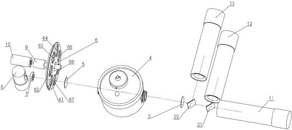
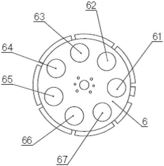
[0024] A beam splitter, such as figure 1 As shown, the spectroscope includes a filter wheel 6 and more than one filter mounted on the filter wheel; the filter wheel uses the one or more filters to realize the detection of incident light by rotating split light. The optical filters are narrow-band optical filters, and the wavelengths of light that can be transmitted by each optical filter are different, and the wavelengths that can be transmitted by each optical filter can be flexibly selected according to actual needs. Preferably, the number of filters is 7, namely figure 1 As shown in 61, 62, 63, 64, 65, 66, and 67, the number of optical filters can be flexibly set according to actual needs.

[0025] Fur...


PUM


Abstract

The invention discloses an optical splitter and a spectrograph using the optical splitter. The optical splitter comprises an optical filtering wheel and more than one optical filtering sheet arranged on the optical filtering wheel, wherein the optical filtering wheel realizes the optical splitting on incident light through more than one optical filtering sheet through rotation, so that the optical splitting on the single-channel or multi-channel optical splitter is realized; the optical splitting efficiency is high; the optical splitting performance of the spectrograph is effectively improved.

Description

technical field [0001] The invention relates to the field of optics, more specifically to a spectrometer and a spectrometer. Background technique [0002] Traditional spectrometers use gratings to split the absorption or emission spectra of multiple elements. The grating has low diffraction efficiency, and its performance is easily affected by the environment. It needs to be sealed and installed, and the installation and debugging are complicated, and the parameter consistency is poor. At the same time, the performance of the raster will get worse and worse after being copied many times. Contents of the invention [0003] (1) Technical problems to be solved [0004] The technical problem to be solved by the present invention is how to improve the light-splitting efficiency and light-splitting effect of the spectrometer, and how to improve the light-splitting performance of the spectrometer. [0005] (2) Technical solutions [0006] In order to solve the above technical ...

Claims


Application Information

Patent Timeline
Patent Type & Authority Applications(China)
IPC IPC(8): G01J3/02G01J3/28
CPCG01J3/0205G01J3/28
Inventor 李国栋陈凯黄鑫李瑞超郝帅杨奇
Owner BEIJING BOHUI INNOVATION TECH
Learn More