A semi-automatic assembly jig

A semi-automatic, jig technology, applied in the jig field, can solve the problems of low work efficiency, increased product defect rate, poor operation stability, etc., to achieve the effect of ensuring quality and high work efficiency

Active Publication Date: 2018-12-28
KENTA ELECTRONIC MFG KUNSHAN CO LTD
View PDF7 Cites 0 Cited by
  • Summary
  • Abstract
  • Description
  • Claims
  • Application Information

AI Technical Summary

Problems solved by technology

However, this operation method has low work efficiency and poor manual operation stability. When installing screws, the screws are easy to damage the product, resulting in an increase in the defective rate of the product.

Method used


Image

  • A semi-automatic assembly jig
  • A semi-automatic assembly jig

Examples


Embodiment Construction

[0013] The preferred embodiments of the present invention will be described in detail below in conjunction with the accompanying drawings, so that the advantages and features of the present invention can be more easily understood by those skilled in the art, so as to define the protection scope of the present invention more clearly.

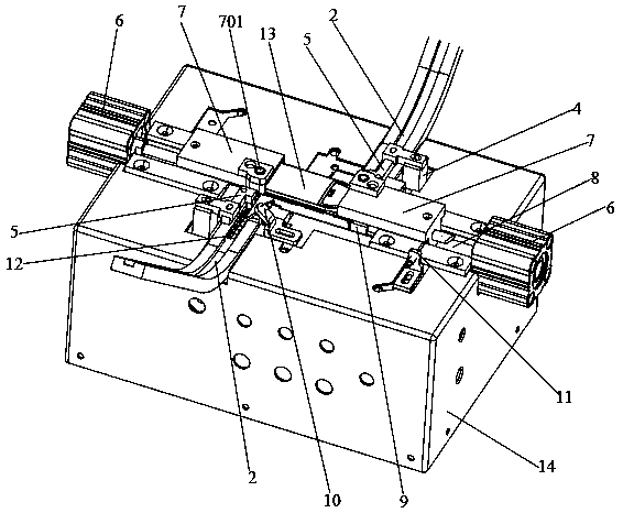
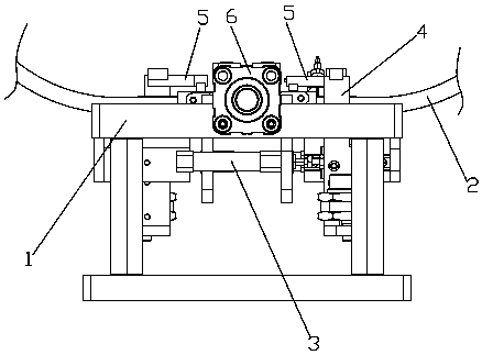
[0014] Such as figure 1 and figure 2 As shown, a semi-automatic assembly jig includes a base 1 on which a cover 14 is arranged. A group of assembling mechanisms are arranged on the left and right parts of the base 1 respectively, and each group of assembling mechanisms includes a feeding assembly and a product fixing assembly. The feeding assembly includes a feeding trough 2, a feeding cylinder 3, a feeding plate 4 and a feeding push block 5. Several accessories 12 are arranged in the feeding trough 2. The feeding cylinder 3 is fixed inside the base 1, and the feeding plate 4 extends into the Inside the base 1 , the feeding plate 4 is connecte...


PUM


Abstract

The invention discloses a semi-automatic assembly tool. The semi-automatic assembly tool comprises a base; two sets of assembly mechanisms are respectively arranged at the left part and the right part of the base; each set of assembly mechanisms includes feeding modules and product fixing module; the feeding modules include grooves, feeding cylinders, feeding plates and feeding push blocks; fittings are arranged in the grooves; the feeding plates extend in the base, and are connected with the feeding cylinders; the feeding push blocks are fixed on the feeding plates for pushing the fittings; each set of product fixing modules includes product fixing cylinders and product fixing blocks; product fixing grooves are formed in the base; the products are arranged in the product fixing grooves; two product fixing blocks positioned at the left part and the right part of the base fix the products; the product fixing grooves are communicated with the grooves; and screw entering holes are formed in the product fixing blocks. The tool can quickly realize fixed assembly of the products and the fittings, is higher in working efficiency, saves both time and labors, cannot damage the products, and guarantees the quality of the products.

Description

technical field [0001] The invention relates to a jig, in particular to a semi-automatic assembly jig. Background technique [0002] In the prior art, when assembling accessories and products, the accessories are manually put into the product, and then screws are screwed in to securely connect the accessories and the product. However, this operation method has low work efficiency and poor manual operation stability. When installing screws, the screws are easy to damage the product, resulting in an increase in the defective rate of the product. Contents of the invention [0003] In order to solve the above technical problems, the purpose of the present invention is to provide a semi-automatic assembly jig, which can easily realize the assembly of accessories, products and screws, saving time and effort. [0004] In order to achieve the above technical purpose and achieve the above technical effect, the present invention is realized through the following technical solutions...

Claims


Application Information

Patent Timeline
Patent Type & Authority Patents(China)
IPC IPC(8): B23P19/06B23P19/00
CPCB23P19/002B23P19/06
Inventor 蔡峻峰骆大江陈建伟
Owner KENTA ELECTRONIC MFG KUNSHAN CO LTD
Why Eureka
Try Eureka