Magnetic transfer device for USB interface

A technology of USB interface and transfer device, applied in the direction of connecting/disconnecting connecting components, coupling device, connection, etc., can solve the problems of easy deformation of the interface, consequential damage to equipment, damage, etc., to achieve the effect of increasing ease of use

Inactive Publication Date: 2016-12-07
张宇星
View PDF4 Cites 2 Cited by
  • Summary
  • Abstract
  • Description
  • Claims
  • Application Information

AI Technical Summary

Problems solved by technology

However, there are also defects such as the interface is easily deformed and damaged, and it is easy to cause the device to drop when the USB peripheral cable is pulled, resulting in joint damage, etc.
And the existing USB interface can only be inserted in a fixed direction when it is connected, so that the user often inserts it several times before it can be successfully connected when using it, which is not convenient enough

Method used


Image

  • Magnetic transfer device for USB interface
  • Magnetic transfer device for USB interface
  • Magnetic transfer device for USB interface

Examples


Embodiment Construction

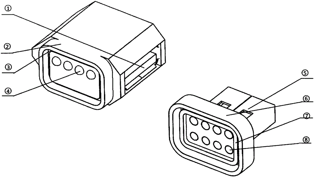
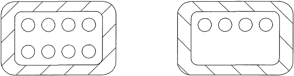
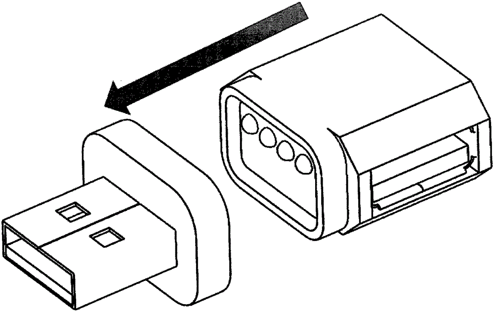
[0014] The magnetic conversion device such as figure 1 shown. The device includes: a USB interface female seat (1), a mobile terminal housing (2), a mobile terminal magnet (3), a mobile terminal contact (4), a USB interface male head (5), a fixed terminal housing (6) , fixed end magnet (7), fixed end contact (8). The inside of the transfer device is physically connected, the eight contacts at the fixed end and the four contacts at the mobile end are respectively in accordance with figure 2 The interface definition diagram shown is connected with the traditional USB male and female connectors respectively. At this point, press the two parts image 3 When the approach shown is close, the two parts will automatically combine to form due to the magnetic attraction Figure 4 Indicates the working status. When turned horizontally by 180 degrees, the two parts of the contacts can still be normally connected in the order required for work. Promptly realized the dual-purpose fun...


PUM


Abstract

The invention relates to a magnetic transfer device for a USB interface, which is characterized in that the magnetic transfer device comprises a USB interface female seat (1), a mobile end shell (2), a mobile end magnet (3), mobile end contacts (4), a USB interface male terminal (5), a fixed end shell (6), a fixed end magnet (7) and fixed end contacts (8), wherein the mobile end magnet (3) and the fixed end magnet (7) are mutually attracted in the case of work to fix the mobile end shell (2) and the fixed end shell (6); and the mobile end contacts (4) and the fixed end contacts (8) are connected for transmitting data. Due to special arrangement of the contacts, when the two parts are attracted, being forward or inverse of the mobile end interface does not influence normal connection. The device is applicable to all machines and peripheral devices adopting the USB interface.

Description

technical field [0001] The invention relates to a USB interface magnetic transfer device, which is used to enhance the safety and usability of the existing USB interface. The device adopts the principle of magnetic adsorption to improve various defects of the traditional USB interface, and is suitable for all existing machines and peripherals using the USB interface. Background technique [0002] The existing USB interface adopts the plug-in connection principle, although it has the advantages of firm connection and low cost. However, there are also defects such as the interface is easily deformed and damaged, and it is easy to cause the device to fall off the ground when the USB peripheral cable is pulled and cause collateral damage. And the existing USB interface can only be inserted in a fixed direction when accessing, so that the user often inserts it repeatedly several times before successfully connecting, which is not convenient enough. [0003] The design of the pre...

Claims


Application Information

Patent Timeline
Patent Type & Authority Applications(China)
IPC IPC(8): H01R13/62H01R31/06
Inventor 张宇星
Owner 张宇星
Why Eureka
Try Eureka