
Mud treatment device for building pile foundation construction

A technology for construction mud and processing equipment, which is applied in wellbore/well components, earthwork drilling, flushing wellbore, etc. It can solve the problems of filter sieve damage, high energy consumption, and failure to meet the needs of energy conservation and environmental protection, etc., to reduce the use of , the effect of reducing energy consumption

Active Publication Date: 2016-12-07
CHONGQING TECH & BUSINESS INST +2
View PDF6 Cites 19 Cited by
  • Summary
  • Abstract
  • Description
  • Claims
  • Application Information

AI Technical Summary

Problems solved by technology

Although this system has achieved the separation of mud and drilled ballast to a certain extent, the disadvantages that still exist in this system are: 1) the system is provided with two filter sieve plates, and all filter sieve plates are arranged in the horizontal direction, although The filtering effect of the filter sieve plate is good, but it is difficult to remove the drilling ballast on the filter screen plate after the filtering operation is completed. The system is equipped with a screw conveyor for the drill ballast removed from the filter screen plate. Since the filter screen plate is located in the horizontal direction In fact, although the screw conveyor is inclined, only a small part of the drill ballast can enter the screw conveyor and be transported out. After a long time, the drill ballast will be deposited on the filter sieve plate, which hinders the subsequent mud filtration. Simultaneously, the phenomenon that the filter sieve plate will be damaged due to the large amount of drilling slag will occur, and the work of the screw conveyor will also consume more energy, which cannot meet the modern energy-saving and environmental protection requirements; 2) vibrators are set on the filter box of the system, thereby Realize the vibration of the whole filter box (including the filter sieve plate), but in order to increase the separation speed of mud and drill ballast, it is only necessary to vibrate the filter sieve plate, so a vibrator is installed on the entire filter box to make the filter box vibrate in the same way It takes a lot of energy, and the filter box will be damaged quickly if it vibrates together for a long time

Method used


Image

  • Mud treatment device for building pile foundation construction
  • Mud treatment device for building pile foundation construction
  • Mud treatment device for building pile foundation construction

Examples


Embodiment 1

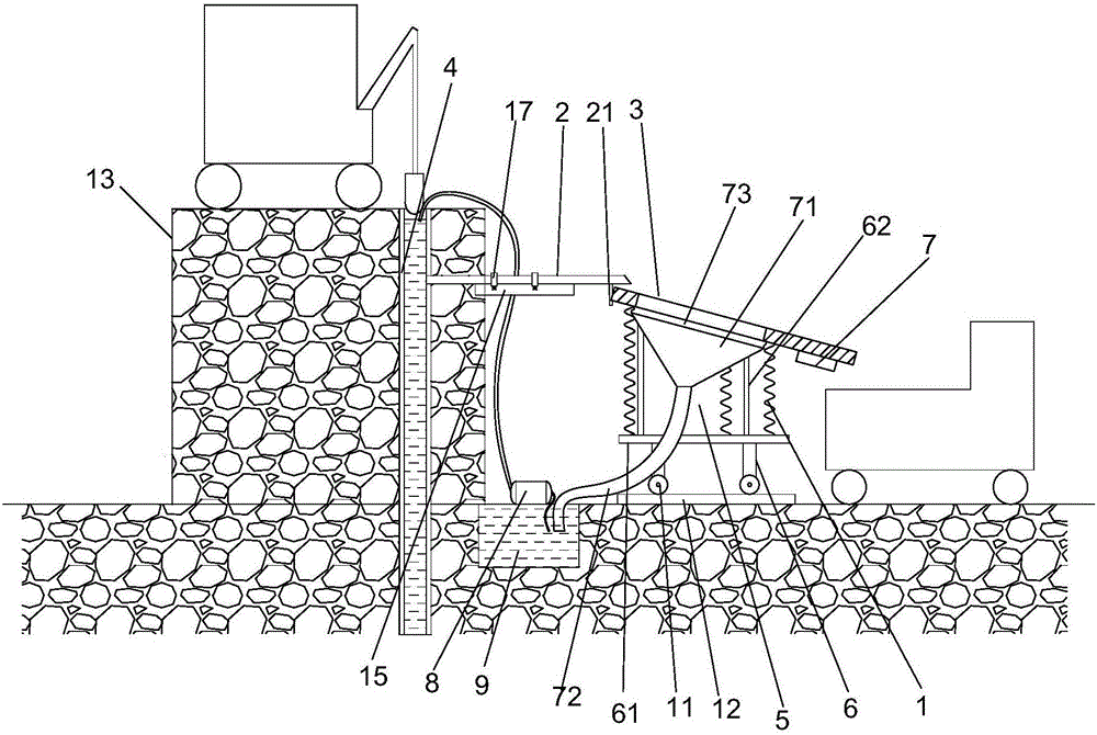
[0023] Such as figure 1 As shown, the present invention proposes a construction mud treatment device for pile foundations, comprising: clean water tank (not shown in the figure), water pump (not shown in the figure), spring 1, sand-water mixing pipeline 2, screen 3, mud Transfer device 5 , support frame 6 , vibrator 7 , mud pump 8 and mud pool 9 .

[0024] Specifically, a clean water tank is arranged beside the sand-water mixing pipeline 2, and the clean water tank is used for buffering clean water.

[0025] The input end of the water pump communicates with the clean water tank to extract clean water.

[0026] The position of the input end of the sand-water mixing pipeline 2 is higher than the position of the output end, and the overflow hole provided on the top of the casing 4 and the output end of the water pump are all connected to the input end of the sand-water mixing pipeline 2, thereby realizing the connection between the sand-water mixing pipeline 2 Internal mixing, ...

Embodiment 2

[0042] The difference between this embodiment and Embodiment 1 is that, in order to remove the residual drill dregs on the screen 3 conveniently, a movable plate 35 and a driving device 36 are arranged on the screen 3 .

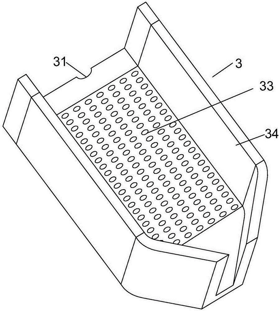
[0043] Such as Figure 4 As shown, specifically, the screen 3 is provided with a movable plate 35 that can slide in the drain of the screen 3, and the screen 3 is provided with a driving device 36 for driving the movable plate 35, and when in the filtering state The movable plate 35 is located on the end face of the input end of the screen cloth 3 .

[0044] Such as Figure 4 as well as Figure 5 As shown, in order to realize the driving of the movable plate 35 by the driving device 36 . Because the drill quarrel on the screen cloth 3 can slide down automatically under the action of gravity, but there are still residual drill dregs on the screen cloth 3, long-term accumulation can cause the screen cloth 3 to be blocked, therefore the movable plate 35 and t...


PUM


Abstract

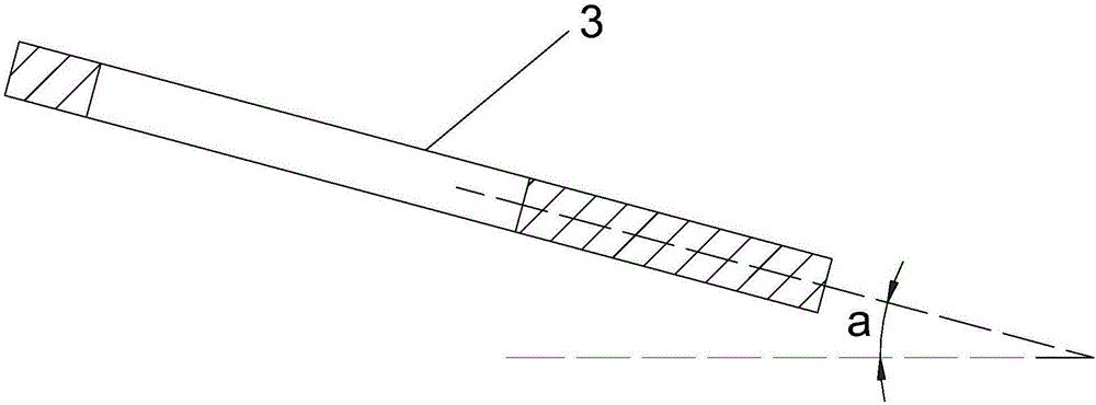
The invention provides a mud treatment device for building pile foundation construction. The mud treatment device comprises a sand pump for pumping mud and drilling slag out of a drilled hole, a clean water tank for storing clean water, a water pump, a sand and water mixing pipeline, a screen and a net rack, wherein the input end of the water pump is communicated with the clean water tank, so that clean water can be pumped; the position of the input end of the sand and water mixing pipeline is higher than that of the output end of the sand and water mixing pipeline, the output end of the sand pump and the output end of the water pump are both connected to the input end of the sand and water mixing pipeline; the screen is of a circular-arc-shaped structure, the input end of the screen is located below the output end of the sand and water mixing pipeline, the position of the input end of the screen is higher than that of the output end of the screen, and an included angle between the axis of the screen and the horizontal line is 20-30 degrees; the net frame comprises at least two diagonal rods, the upper end of each diagonal rod is fixed with the edge of the screen, and the lower end of each diagonal rod is connected to a vibrating plate. The med treatment device has the following benefit: automatic discharge of drilling slag is realized after mud separation.

Description

technical field [0001] The invention relates to a device used in pile foundation construction, in particular to a construction mud treatment device for pile foundation construction. Background technique [0002] With the development of the economy and the acceleration of urbanization, the construction industry is developing more and more rapidly, and more and more buildings are built on complex foundations. Pile foundation engineering has become one of the most commonly used forms of construction. For complex foundations such as soft foundations, block stones, or super-deep and super-large-diameter pile foundations, the mechanical mud retaining wall forming technology is used more and more as a mature technology during construction. In the prior art, during construction, a mud pool is set on the site plane for mixing mud or as a circulating mud pool. The mud index in the borehole is repeatedly measured along with the drilling footage, and the mud pump is used to replenish th...

Claims


Application Information

Patent Timeline
Patent Type & Authority Applications(China)
IPC IPC(8): E21B21/06
CPCE21B21/062E21B21/066
Inventor 王清江陈怡宏李志强周瑜王悦张意谷杰
Owner CHONGQING TECH & BUSINESS INST
Learn More