A special construction equipment for geotechnical anti-landslide retaining wall

A technology for construction equipment and retaining walls, applied in the field of geotechnical engineering, can solve the problems of low construction efficiency, high labor intensity, slow grabbing speed, etc., and achieves improved work stability, good tensioning effect, and fast grabbing speed. Effect

Inactive Publication Date: 2018-03-02
江苏省中成建设工程总公司
View PDF7 Cites 0 Cited by
  • Summary
  • Abstract
  • Description
  • Claims
  • Application Information

AI Technical Summary

Problems solved by technology

[0003] In order to solve the above problems, the present invention provides a special construction equipment for geotechnical anti-landslide retaining walls, which can solve the problems of the existing artificial stacking methods of retaining walls that require manual full-process operation, low construction efficiency, serious safety hazards, and the need for manual construction. Grabbing masonry, labor-intensive, slow grabbing speed, low grabbing efficiency, no left and right limits in the conveying process, prone to hidden dangers of masonry rolling and poor conveying effect, etc., can realize automatic grabbing of masonry Conveying function, high construction efficiency, no safety hazards, left and right limit during the entire conveying process, eliminating the hidden danger of rolling during the masonry conveying process, and has automatic rotation to grab and release the masonry, and the grabbing speed is fast and high grabbing efficiency

Method used


Image

  • A special construction equipment for geotechnical anti-landslide retaining wall
  • A special construction equipment for geotechnical anti-landslide retaining wall
  • A special construction equipment for geotechnical anti-landslide retaining wall

Examples


Embodiment Construction

[0022] In order to make the technical means, creative features, goals and effects achieved by the present invention easy to understand, the present invention will be further described below in conjunction with specific illustrations.

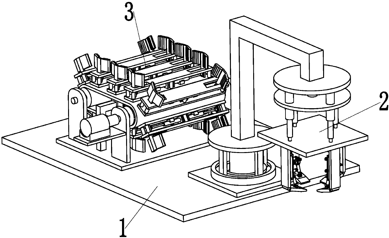
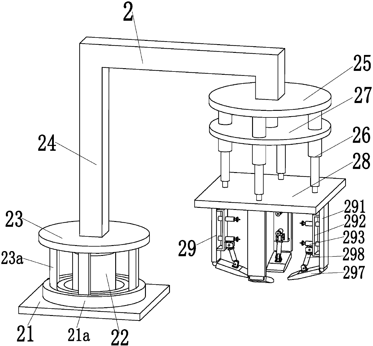
[0023] Such as Figure 1 to Figure 9 As shown, a special construction equipment for geotechnical anti-landslide retaining walls includes a base 1, and a hydraulic grabbing device 2 is installed on the right side of the upper end surface of the base 1, and the hydraulic grabbing device 2 can realize the present invention to masonry. The hydraulic automatic grabbing function does not require manual grabbing and placement, the grabbing speed is fast, and the grabbing efficiency is high. The limit conveying device 3 is installed in the middle of the upper end surface of the base 1, and the limit conveying device 3 can realize the stable limit of the mortar masonry. Position conveying function, there are left and right limit positions in the whole co...


PUM


Abstract

The invention relates to special construction equipment for a rock-soil landslide prevention retaining wall. The special construction equipment comprises a base; a hydraulic grabbing device is mounted on the right side of the upper end surface of the base and can achieve a hydraulic automatic grabbing function for grouted rubble, manual grabbing and placing are needless, the grabbing speed is high, and the grabbing efficiency is high; and a limiting conveyer is mounted in the middle of the upper end surface of the base and can achieve a stable limiting conveying function for the grouted rubble, limiting in the left and right direction exists in the whole grouted rubble conveying process, hidden tumbling dangers of the grouted rubble in the conveying process are eliminated, the conveying effect is good, and manual operation is needless. The hydraulic grabbing device comprises a rotating bottom plate welded to the upper end surface of the base. A rotating motor is mounted in the middle of the upper end surface of the rotating bottom plate through a motor base. A rotating platform is fixedly mounted on an output shaft of the rotating motor. Four T-shaped slide posts are evenly arranged on the lower end surface of the rotating platform in the axial direction. According to the special construction equipment for the rock-soil landslide prevention retaining wall, the function that the grouted rubble is automatically grabbed and conveyed can be achieved.

Description

technical field [0001] The invention relates to the technical field of geotechnical engineering, in particular to a special construction equipment for geotechnical anti-landslide retaining walls. Background technique [0002] There are generally retaining walls on both sides of the expressway section and the urban highway section near the mountain. The types of retaining walls are divided into two types: masonry retaining walls and concrete retaining walls. The main functions of the retaining walls are: 1. Support roadbed filling or hillside soil; 2. Prevent filling or soil deformation and instability; It is located next to the mountain, and the raw materials of masonry are abundant, so the masonry retaining wall is mainly used. The existing masonry retaining wall is mainly built by manual methods. First, the processed masonry is artificially Grab and place it in the transport trolley, the operator pushes the transport trolley to the conveying equipment, pours the masonry i...

Claims


Application Information

Patent Timeline
Patent Type & Authority Patents(China)
IPC IPC(8): E02D29/02
CPCE02D29/0283
Inventor 刘刚戚旭东杨军黄涛常伟单文君沈娟
Owner 江苏省中成建设工程总公司
Why Eureka
Try Eureka