
Automobile conveying device for automobile detection system and automobile detection system

A conveying device and vehicle detection technology, applied in conveyors, mechanical conveyors, transportation and packaging, etc., can solve problems such as misjudgment by staff and affecting image quality

Inactive Publication Date: 2016-12-07
BEIJING HUALIXING SCI TECH DEV
View PDF0 Cites 5 Cited by
  • Summary
  • Abstract
  • Description
  • Claims
  • Application Information

AI Technical Summary

Problems solved by technology

[0002] At present, the vehicle inspection system uses a chain conveyor to transport the vehicle to be inspected. The radiation source is located above the chain conveyor, and the detection device is located below and on both sides of the chain conveyor. During detection, the ray beam will pass through the chain conveyor. As a result, the local structure of the chain conveyor device will appear on the scanned image, which will block the scanned image of the vehicle to a certain extent, seriously affect the image quality, and easily lead to misjudgment by the staff

Method used


Image

  • Automobile conveying device for automobile detection system and automobile detection system
  • Automobile conveying device for automobile detection system and automobile detection system
  • Automobile conveying device for automobile detection system and automobile detection system

Examples


Embodiment Construction

[0043] In order to understand the above-mentioned purpose, features and advantages of the present invention more clearly, the present invention will be further described in detail below in conjunction with the accompanying drawings and specific embodiments. It should be noted that, in the case of no conflict, the embodiments of the present application and the features in the embodiments can be combined with each other.

[0044] In the following description, many specific details are set forth in order to fully understand the present invention. However, the present invention can also be implemented in other ways than described here. Therefore, the protection scope of the present invention is not limited by the specific implementation disclosed below. Example limitations.

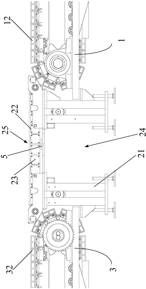
[0045] Such as Figure 1 to Figure 5 As shown, the embodiment of the first aspect of the present invention provides a vehicle conveying device for a vehicle detection system. The vehicle conveying device inc...


PUM


Abstract

The invention provides an automobile conveying device and an automobile detection system. The automobile conveying device comprises a first conveying assembly unit, a middle conveying assembly unit and a second conveying assembly unit, wherein the first conveying assembly unit, the middle conveying assembly unit and the second conveying assembly unit are arranged on the straight line and have the coincident conveying direction. The middle conveying assembly unit is located between the first conveying assembly unit and the second conveying assembly unit. According to the scheme, the automobile conveying device is divided into three parts; the middle conveying assembly unit is located below a radiation source of the automobile detection system and comprises a support, a first conveying part and a second conveying part; a horizontal probing device of the automobile detection system is installed in a reserved mounting space of the support; and a gap is reserved between the first conveying part and the second conveying part and aligns with a ray outlet of the radiation source and a ray inlet of the horizontal probing device, ray beams emitted by the radiation source just penetrate through the gap so that the conveying device cannot appear on a scanning pattern, consequently, the problem of pattern shielding is solved, and the quality of the scanning pattern is greatly improved.

Description

technical field [0001] The present invention relates to the field of conveying devices, more specifically, to a vehicle conveying device used in a vehicle detection system, and a vehicle detection system with the vehicle conveying device. Background technique [0002] At present, the vehicle inspection system uses a chain conveyor to transport the vehicle to be inspected. The radiation source is located above the chain conveyor, and the detection device is located below and on both sides of the chain conveyor. During detection, the ray beam will pass through the chain conveyor. As a result, the local structure of the chain conveyor device will appear on the scanned image, which will block the scanned image of the vehicle to a certain extent, seriously affect the image quality, and easily lead to misjudgment by the staff. Contents of the invention [0003] The present invention aims to solve at least one of the technical problems existing in the prior art. [0004] Therefo...

Claims


Application Information

Patent Timeline
IPC IPC(8): B65G37/00
CPCB65G37/00
Inventor 赵杰曲海波张晓东
Owner BEIJING HUALIXING SCI TECH DEV
Learn More