
Cleaning system of multi-rotor unmanned aerial vehicle

A multi-rotor unmanned aerial vehicle and cleaning system technology, applied in the field of aerial work machinery, can solve the problems of inability to clean exterior walls, obstacles, low cleaning efficiency, etc., to reduce the number of employees, improve cleaning efficiency, and high cleaning efficiency. Effect

Inactive Publication Date: 2016-12-07
GUANGDONG RONGQE INTELLIGENT TECH CO LTD
View PDF6 Cites 13 Cited by
  • Summary
  • Abstract
  • Description
  • Claims
  • Application Information

AI Technical Summary

Problems solved by technology

[0002] With the acceleration of urbanization, many office buildings have been built in many cities. Most of the exteriors are decorated with glass or stainless steel. After a long time, glass or stainless steel needs to be cleaned. However, it is impossible to clean the external walls indoors. At present, it is mainly Workers working at heights use ropes to hoist the exterior wall from the roof to clean the exterior wall. Not only is the cleaning efficiency low, but also the risk factor is high. Although there are similar exterior wall cleaning robots, the exterior wall cleaning robot is affected by the shape of the wall and has a limited scope of application. The flexibility is low, and the ground cleaning machine is limited by height and can only work at low altitudes. In addition to the disadvantages of cleaning the outer walls of tall buildings, there are also many obstacles to the cleaning of power towers and outdoor wind power towers.

Method used


Image

  • Cleaning system of multi-rotor unmanned aerial vehicle
  • Cleaning system of multi-rotor unmanned aerial vehicle
  • Cleaning system of multi-rotor unmanned aerial vehicle

Examples


Embodiment Construction

[0015] The specific embodiment of the present invention will be described in further detail by describing the embodiments below with reference to the accompanying drawings, the purpose is to help those skilled in the art to have a more complete, accurate and in-depth understanding of the concept and technical solutions of the present invention, and contribute to its implementation.

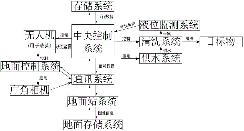
[0016] Such as figure 1 As shown, the present invention is a multi-rotor UAV cleaning system, which aims to be used for high-altitude cleaning operations, improve cleaning efficiency, and reduce the number of people working at high altitudes.

[0017] Specifically, if Figure 1 to Figure 3 As shown, including central control system, UAV 1, storage system, communication system, ground station system, ground storage system, ground control system, water supply system, cleaning system and liquid level monitoring system, wherein UAV 1, storage system The communication system is connected bidirectiona...


PUM


Abstract

The invention discloses a cleaning system of a multi-rotor unmanned aerial vehicle. The system comprises a central control system, the unmanned aerial vehicle, a storage system, a communication system, a ground station system, a ground storage system, a water supply system, a cleaning system and a liquid level monitoring system. The unmanned aerial vehicle, the storage system, the communication system are connected with a central control system in two directions. The water supply system, the cleaning system and the liquid level monitoring system are connected with the central control system in signal direction. The ground control system is connected with the unmanned aerial vehicle in signal direction. The communication system is connected with the ground station system in two directions. The ground station system is connected with the ground storage system in two directions. A wide-angle lens camera is arranged on the unmanned aerial vehicle. By an ordinary spray head and a high-pressure spray head of the cleaning system and the presence of a steering engine, cleaning efficiency is improved and cleaning degree is ensured. The structures of water tanks of the cleaning system are symmetrical so that stability of the unmanned aerial vehicle during cleaning is ensured.

Description

technical field [0001] The invention belongs to the technical field of aerial work machinery, in particular, the invention relates to a multi-rotor unmanned aerial vehicle cleaning system. Background technique [0002] With the acceleration of urbanization, many office buildings have been built in many cities. Most of the exteriors are decorated with glass or stainless steel. After a long time, glass or stainless steel needs to be cleaned. However, it is impossible to clean the external walls indoors. At present, it is mainly Workers working at heights use ropes to hoist the exterior wall from the roof to clean the exterior wall. Not only is the cleaning efficiency low, but also the risk factor is high. Although there are similar exterior wall cleaning robots, the exterior wall cleaning robot is affected by the shape of the wall and has a limited scope of application. The flexibility is low, and the floor cleaning machine is limited by height, so it can only work at low alti...

Claims


Application Information

Patent Timeline
Patent Type & Authority Applications(China)
IPC IPC(8): B64F5/00B64C27/08
CPCB64C27/08B64U10/10
Inventor 白朝顺
Owner GUANGDONG RONGQE INTELLIGENT TECH CO LTD
Learn More