Connecting structure of engineering mechanical chassis

A technology for connecting structures and construction machinery, which is applied in the substructure, transportation and packaging, vehicle parts, etc., can solve the problems of limited bearing capacity, stress concentration, and single load-bearing structure, and achieve reduced welding costs, less stress concentration, and reliable connections sex high effect

Active Publication Date: 2016-12-07
XCMG EXCAVATOR MACHINERY
View PDF6 Cites 0 Cited by
  • Summary
  • Abstract
  • Description
  • Claims
  • Application Information

AI Technical Summary

Problems solved by technology

Although this structure is detachable, there are the following problems: First, because the size of the H-frame structure is limited by the height of the chassis of the whole machine, its structural strength and rigidity are difficult to be guaranteed. This phenomenon is especially obvious in large-scale construction machinery
Secondly, due to this connection form, only the upper plane of the longitudinal beam and the H-frame cooperate to carry the load, the load-bearing structure is relatively simple, and it is easy to cause stress concentration at the connection part, the load-bearing capacity is limited, and the reliability and stability are not strong.
[0004] In addition to the lap connection method, there are also some construction machinery chassis where the H-frame is inserted into the longitudinal beam. This type of connection will greatly weaken the structural strength of the longitudinal beam, and the application range is limited. Where the load is severe

Method used


Image

  • Connecting structure of engineering mechanical chassis
  • Connecting structure of engineering mechanical chassis
  • Connecting structure of engineering mechanical chassis

Examples


Embodiment Construction

[0020] The present invention will be further described below in conjunction with accompanying drawing.

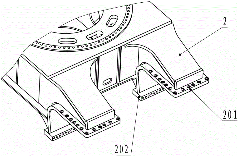
[0021] Such as Figure 1 to Figure 3 As shown, a construction machinery chassis connection structure includes a longitudinal beam 1 and an H frame 2, and also includes an H frame bending connecting plate 201 and an H frame horizontal connecting plate 202 for connecting the H frame 2 to the longitudinal beam 1, and the H frame The frame bending connecting plate 201 and the H frame horizontal connecting plate 202 are welded to form a Z-shaped structure; the H frame bending connecting plate 201 is used as the Z-shaped horizontal folding upper part and the H frame horizontal connecting plate 202 as the Z-shaped horizontal bottom edge The welding is in a Z-shaped structure; the H frame bending connecting plate 201 is welded under one end of the H frame 2; the H frame 2 is fixedly connected with the longitudinal beam top plate 101 of the longitudinal beam 1 through the H frame be...


PUM


Abstract

The invention discloses a connecting structure of an engineering mechanical chassis. The connecting structure comprises an H frame, a longitudinal beam, H frame bending connecting plates and an H frame horizontal connecting plate, wherein the H frame bending connecting plates and the H frame horizontal connecting plate are used for enabling the H frame and the longitudinal beam to be connected; the H frame bending connecting plates are welded to the H frame horizontal connecting plate, so that a Z-shaped structure is formed; the H frame bending connecting plates are welded under one end of the H frame; and the H frame is fixedly connected with a longitudinal beam top plate of the longitudinal beam in a vertical direction through the H frame bending connecting plates, and is fixedly connected with a longitudinal beam bottom plate of the longitudinal beam in a horizontal direction through the H frame horizontal connecting plate. According to the connecting structure disclosed by the invention, the connection of the H frame and the longitudinal beam is formed by the top surfaces and the side surfaces; a stereoscopic connecting structure is uniform in bearing, and stress concentration is not liable to exist; the structural strength of the connection is greatly enhanced, and the connecting reliability is high; under the premise that the total height of the chassis is guaranteed, an enough structural space is provided for the H frame, so that the situation that the H frame has enough structural strength is guaranteed; the structure is simple, and the connecting manner is mainly embodied by one bending plate; and the number of welding structures is reduced, so that welding cost is reduced.

Description

technical field [0001] The invention relates to a connection structure, in particular to a construction machinery chassis connection structure, which belongs to the technical field of construction machinery. Background technique [0002] At present, the construction machinery chassis, especially the crawler type construction machinery chassis, generally consists of three parts: the H frame placed in the middle for connecting the boarding vehicle and the longitudinal beams on the left and right sides used to arrange the walking system. For the chassis of large-scale construction machinery, due to its large dead weight and large lateral peripheral dimensions, it is not convenient for overall transportation, so a detachable chassis is required. [0003] In the existing detachable construction machinery chassis, the main form is that the H frame is lapped on the longitudinal beam. The H frame of this structure is completely placed on the top surface of the longitudinal beam, and...

Claims


Application Information

Patent Timeline
Patent Type & Authority Applications(China)
IPC IPC(8): B62D21/02
CPCB62D21/02
Inventor 付相华吴金锋丁跃进渠立红李乃柱
Owner XCMG EXCAVATOR MACHINERY
Why Eureka
Try Eureka