
Method for detecting state of gap of DC switch

A state detection and turnout technology, which is applied in the locking mechanism for turnout, railway car body parts, railway signal and safety, etc., can solve the problems of increasing cost and technical difficulty, high bandwidth of image transmission, and easy safety risks , to achieve the effect of difficult installation and construction, reduced difficulty of operation and long service life

Inactive Publication Date: 2016-12-07
MIANYANG WEIBO ELECTRONICS
View PDF6 Cites 11 Cited by
  • Summary
  • Abstract
  • Description
  • Claims
  • Application Information

AI Technical Summary

Problems solved by technology

Installing video equipment inside the turnout point machine is likely to bring safety risks; it is necessary to provide power cables indoors, which is not convenient for construction; image transmission requires high bandwidth, which increases costs and technical difficulties; this detection technology is also easily recognized by judges Influenced by human factors such as level and work experience

Method used


Image

  • Method for detecting state of gap of DC switch

Examples


Embodiment 1

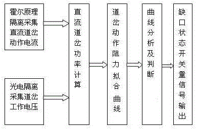
[0023] like figure 1 As shown, the present invention includes a method for detecting the gap state of a DC turnout, comprising the following steps:

[0024] Step A) isolating and collecting the real-time operating current I of the DC switch, and collecting the real-time operating voltage U of the switch;

[0025] Step B) Calculate the real-time DC switch power P=U×I according to the real-time operating current I measured in step A) and the real-time operating voltage U;

[0026] Step C) According to the real-time DC turnout power P calculated in step B) and the speed V of the switch machine, calculate the action resistance of the turnout F=P÷V, thereby drawing the fitting curve of the action resistance of the turnout; wherein the speed of the switch machine V can know when the switch machine is working.

[0027] Step D) Analyzing the fitting curve of the switch action resistance obtained in step C), and judging whether the resistance fitting curve is the normal action state ...

Embodiment 2

[0033]The present embodiment is preferably as follows on the basis of embodiment 1: due to the continuous and linear readings, simple method, long service life, and the ability to measure the magnetic field of small spaces and small gaps when using the Hall effect to measure the magnetic field, it is very suitable for use It is used to collect the operating current of the DC turnout; the operating voltage of the turnout is collected by means of photoelectric isolation, which can isolate the interference source from the easy-interference source, avoid the influence of the easy-interference source on the voltage to be measured, and ensure the accuracy of the final measurement result. Therefore, in step A ) The real-time operating current I of the DC turnout adopts the isolation and collection of the Hall principle, and the real-time working voltage U of the turnout adopts the photoelectric isolation collection, which is simple in engineering construction and safe in monitoring.

...


PUM


Abstract

The invention discloses a method for detecting the state of a gap of a DC switch. The method comprises the following steps of step A) performing isolated collection on a real-time action current I of the DC switch, and collecting a real-time working voltage U of the switch; step B) according to the real-time action current I and the real-time working voltage U, performing calculation so as to obtain a real-time power P=U*I of the DC switch; step C) according to the real-time power P of the DC switch and a speed V of a switch machine, performing calculation to obtain a resistance F=P / V of switch movement, so as to draw a resistance fitting curve of the switch movement; step D) analyzing the resistance fitting curve of the switch movement, and judging whether the resistance fitting curve is a normal movement state of the gap of the switch machine or not; and step E) according to the movement state of the gap of the switch machine judged in the step D), outputting a switching value signal of the corresponding gap state. According to the method disclosed by the invention, mounting video equipment, providing an additional electricity supply circuit and providing a high wideband are not needed, and the method is simple in construction, safe in monitoring, low in cost and accurate in testing results.

Description

technical field [0001] The invention relates to the field of railways, in particular to a detection method for a gap state of a DC turnout. Background technique [0002] In the railway turnout system, the DC turnout switch machine is used to drive the turnout to realize the conversion of the train track. The DC switch point machine is used to pull the switch gap. The switch gap is the gap between the moving track and the fixed track after the switch machine is pulled. If the gap is too large, it will cause safety accidents such as derailment and rollover of the train when it travels to the switch. The conventional detection technology for the detection of the gap characteristics of the existing DC turnout point machine is: install video equipment inside the switch point machine, provide an additional power supply cable through the room, transmit the video information to the monitoring terminal through the power supply cable, and manually Monitor the notch characteristics of...

Claims


Application Information

Patent Timeline
IPC IPC(8): B61L5/10B61L23/04
CPCB61L5/10B61L23/04
Inventor 雍鸿程戚继飞
Owner MIANYANG WEIBO ELECTRONICS
Learn More