
Horizontal biomass particle thermal energy generation purifier

A biomass particle and purifier technology, applied in fluid heaters, lighting and heating equipment, blasting equipment, etc., can solve the problems of flue gas escape, excessive flue gas concentration, unsuitable installation and use, etc., to achieve smooth and smooth operation , Reasonable operating space, the effect of accurate shape and position datum

Inactive Publication Date: 2017-11-17
SIPING CITY DONGSHENG HEAT EXCHANGER MFG CO LTD
View PDF6 Cites 0 Cited by
  • Summary
  • Abstract
  • Description
  • Claims
  • Application Information

AI Technical Summary

Problems solved by technology

[0004] Some biomass hot blast stoves use the method of adding biomass particles directly from the furnace door to the combustion chamber. Due to the need to open the furnace door frequently, it often causes problems such as unstable temperature in the combustion chamber, insufficient volatile matter precipitation, and excessive inhalable particles. At the same time, because the furnace door is opened during combustion, the smoke easily escapes from the furnace door, which is not suitable for indoor installation and use, which limits the application range of the product
[0005] Some biomass energy hot blast stoves use a fixed air volume blower to blow oxygen directly to the combustion layer, which often causes problems such as uneven oxygen supply in the combustion chamber, insufficient combustion of biomass particles, and easy escape of combustible particles with the wind, which directly affects Product technical quality performance
[0006] Most biomass hot blast stoves are not equipped with separation and purification devices. Generally, hot air is directly sent from the air outlet of the combustion chamber to provide hot air, which often causes problems such as excessive inhalable particles and flue gas concentration.

Method used

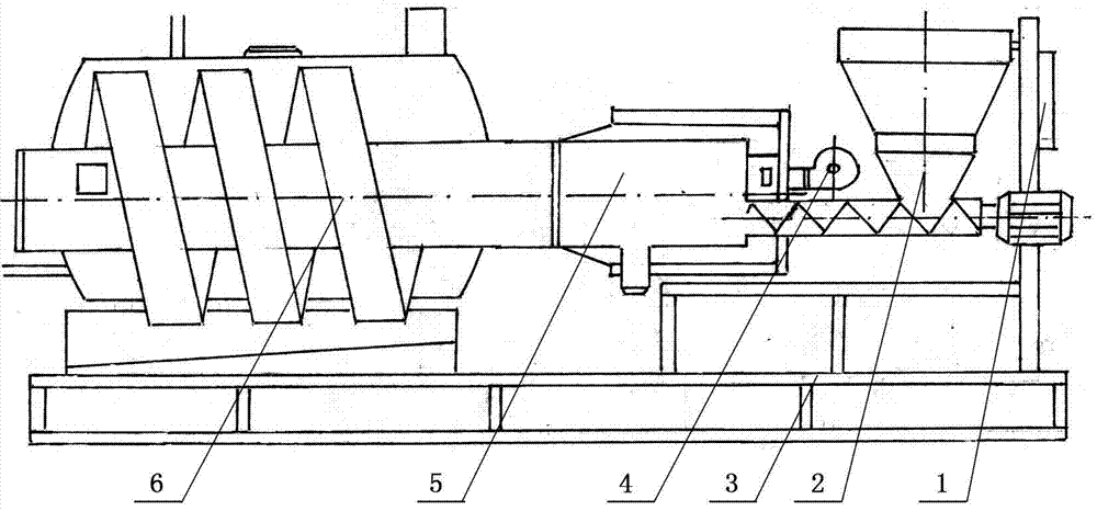
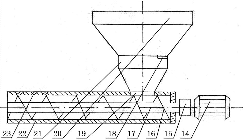

Image

  • Horizontal biomass particle thermal energy generation purifier
  • Horizontal biomass particle thermal energy generation purifier
  • Horizontal biomass particle thermal energy generation purifier

Examples


Embodiment approach

[0053] as attached figure 1 As shown, the horizontal biomass particle heat generation purifier designed in this patent includes a complete machine frame (3), a feeding device (2), an oxygen supply device (4), a particle combustion chamber (5), a separation and purification Heating device (6), manipulation controller (1).

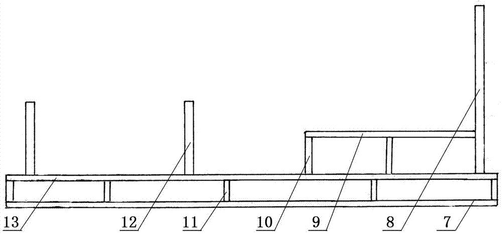
[0054] as attached figure 2 As shown, the complete machine frame (3) includes a base, a door frame, and a bracket. The base is welded and fixed into a chassis of frame structure by bottom beams (7) and cross beams, and is welded and fixed into a base plate of frame structure by base beams (13) and cross beams, and then welded by side columns (11) on both sides. It is connected and fixed as a rigid whole in the form of a three-dimensional grid frame structure. The door frame is composed of left and right two groups of door frames. Each group of door frames includes two front and rear door posts (12) and arc-shaped joists. The lower ends of each group of f...


PUM


Abstract

The patent discloses a horizontal biomass particle thermal energy generating purifier, which includes a complete machine frame, a feeding device, an oxygen supply device, a particle combustion chamber, a separation and purification heating device, and an operating controller. The thermal energy generation purifier adopts a number of innovative technical measures in key core technical contents such as material supply, oxygen delivery, combustion, separation and purification, etc. Oxygen full combustion, cyclone water suction separation and purification, feeding and oxygen matching and coordination, and other operating functions have better solved the problems of uneven oxygen supply in the combustion chamber, insufficient particle combustion, low hot air temperature, and Technical problems such as excessive emission of inhalable particles and smoke; it can meet the winter heating needs of large-scale production and living places such as production workshops, shopping malls, and warehouses in the northern region, and can also be adapted to drying production operations such as painting, grain, food, chemicals, and medicine. Technical requirements for using hot air in places.

Description

technical field [0001] The invention relates to thermal equipment, in particular to a horizontal biomass particle heat generation purifier which uses biomass particles as fuel and can simultaneously provide users with high-temperature clean hot air and domestic hot water services. Background technique [0002] At present, my country's total annual energy consumption is close to 2.5 billion tons of standard coal, becoming the second largest energy consumer in the world. However, my country's petrochemical energy resource reserves are relatively short. With the continuous advancement of my country's industrialization and urbanization, Especially with the sustained and stable growth of the national economy, the contradiction between supply and demand of petrochemical energy will become increasingly prominent. It is an inevitable choice for the national energy strategy to realize the diversification of energy supply and to expand multiple ways to solve energy shortages. Both sci...

Claims


Application Information

Patent Timeline
Patent Type & Authority Patents(China)
IPC IPC(8): F24H6/00F23K3/00F23L5/02F23J15/02
Inventor 姜万臣莫莉姜珊
Owner SIPING CITY DONGSHENG HEAT EXCHANGER MFG CO LTD
Learn More