
A continuous cap feeding device

A technology for feeding caps and sliding caps, applied in the direction of conveyors, flanged bottle caps, conveyor objects, etc., can solve problems such as hindering manual operation and affecting efficiency, and achieve timely and effective reset, improve efficiency, and high production efficiency Effect

Active Publication Date: 2018-10-19
海口尚维科技有限公司
View PDF6 Cites 0 Cited by
  • Summary
  • Abstract
  • Description
  • Claims
  • Application Information

AI Technical Summary

Problems solved by technology

But when it is opened in this way, the movable cover plate stands on the sliding cover groove. When the bottle cap is taken manually, the movable cover plate will hinder the manual operation and affect the efficiency; if the bottle cap is taken automatically, the problem will be more prominent.

Method used


Image

  • A continuous cap feeding device
  • A continuous cap feeding device
  • A continuous cap feeding device

Examples


Embodiment 2

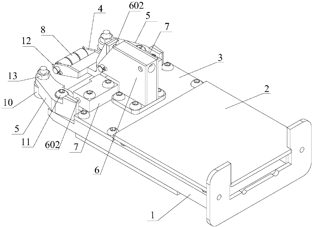
[0036] see Figures 5 to 6 The difference between this embodiment and Embodiment 1 is that a stopper 14 for adjusting the swing angle of the front swing arm 4 is provided between the front swing arm 4 and the fixed plate 3, and the stop member 14 runs through the The front swing arm 4 is installed on the fixed plate 3 . The limiting component 14 can be a screw, a screw or a bolt. Adjusting the height of the stopper 14 can adjust the swing angle range of the front swing arm 4 up and down, so that the continuous cap feeding device of the present invention is suitable for conveying bottle caps of different heights, making the application more extensive.

Embodiment 3

[0038] see Figures 7 to 8 The difference between this embodiment and Embodiment 2 is that the cover plate 2 is provided with several hollow grooves 200, and the cover plate 2 is fixed on the sliding cover groove 1 by magnetic adsorption. The periphery of the cover plate 2 is provided with a first adsorption groove 201, the first adsorption groove 201 is provided with a first adsorption body 202, and the sliding cover groove 1 is provided with a corresponding to the first adsorption groove 201 The second adsorption groove 203 , the second adsorption body 204 is arranged in the second adsorption groove 203 , and the first adsorption body 202 is connected to the second adsorption body 204 by magnetic adsorption. Wherein, the first adsorbent 202 and the second adsorbent 204 are both magnets; or the first adsorbent 202 is a magnet, and the second adsorbent 204 is a ferromagnetic metal body; or the first adsorbent 202 is The ferromagnetic metal body, the second adsorption body 204...

Embodiment 4

[0042] see Figure 9 The difference between this embodiment and Embodiment 2 is that the cover plate 2 is provided with several hollow grooves 200, and the cover plate 2 is fixed on the sliding cover groove 1 by magnetic adsorption. The cover plate 2 is a ferromagnetic metal body, and the sliding cover groove 1 is provided with a magnetic adsorption part 100, and the magnetic adsorption part 100 is a magnet. In this embodiment, the cover plate 2 is fixed on the sliding cover groove 1 by magnetic adsorption, forming a movable cover plate 2, which can be completely taken out and covered with the cover plate 2, without being left in the sliding cover groove 1 in the traditional way. Therefore, it will not hinder the operator from adjusting or taking out the bottle cap, and its operability is strong, which can improve the efficiency of specific use.

[0043] In other embodiments, it may also be that the sliding cover groove 1 is a ferromagnetic metal body, and the cover plate 2 i...


PUM


Abstract

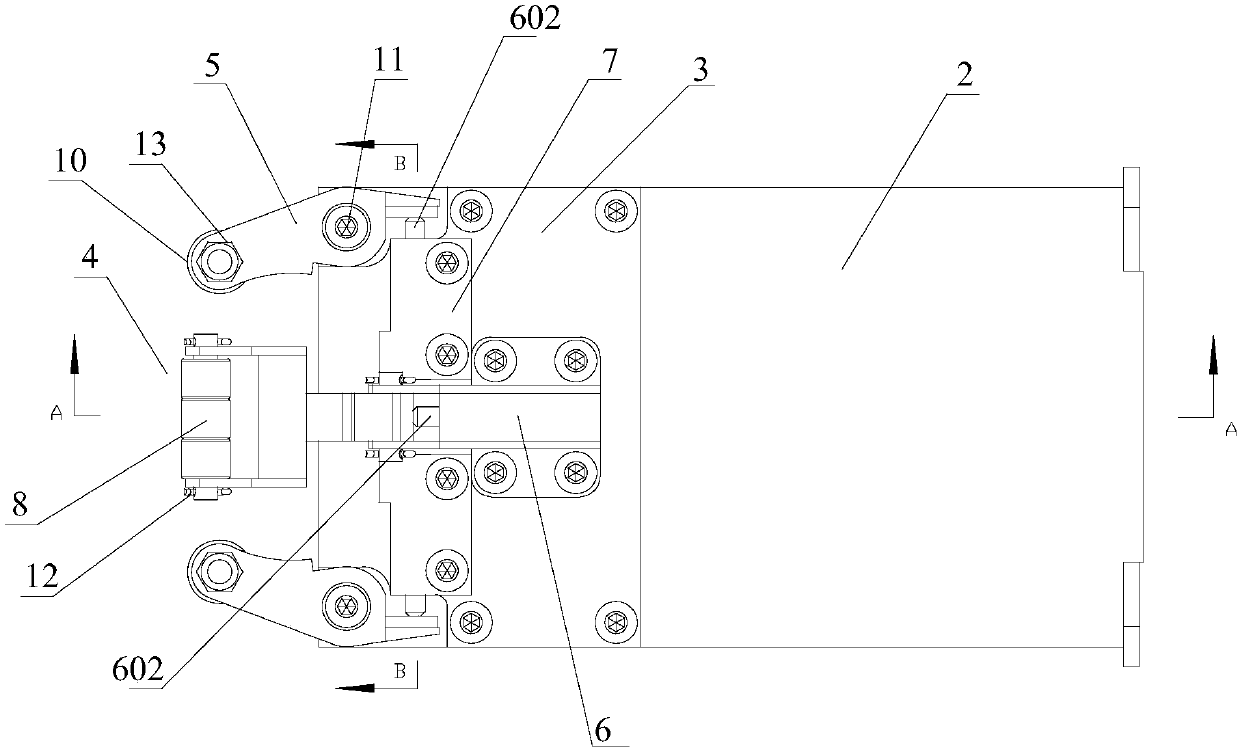
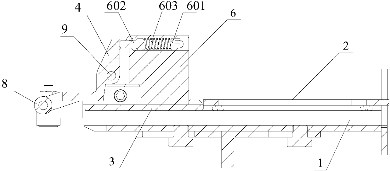
The invention provides a continuous cap feeding device which comprises a cap sliding trough, a cover plate, a fixing plate, a front swing arm and lateral swing arms, wherein the cover plate and the fixing plate are arranged on the cap sliding trough. The front swing arm is located in the middle of the output direction of the cap sliding trough, and the lateral swing arms are mounted on the two sides of the output direction of the cap sliding trough correspondingly and distributed symmetrically. A first spring seat is arranged in the middle of the fixing plate, and second spring seats are arranged on the two sides of the fixing plate correspondingly. A first spring reset mechanism is arranged in the first spring seat, and second spring reset mechanisms are arranged in the second spring seats. A plurality of first wheels rotating in the horizontal direction are arranged at the front end of the front swing arm, and the rear end of the front swing arm is connected with the first spring reset mechanism. Second wheels rotating in the vertical direction are arranged at the front ends of the lateral swing arms, and the rear ends of the lateral swing arms are connected with the second spring reset mechanisms. According to the continuous cap feeding device provided by the invention, bottle caps are not damaged and are smoothly settled, the bottle cap percent of pass is increased, and production efficiency is improved.

Description

technical field [0001] The invention relates to the technical field of packaging equipment, in particular to a continuous cap feeding device. Background technique [0002] The continuous cap feeding device is widely used in the production and packaging of pharmaceutical, food, daily chemical products and other industries. It is mainly used for continuous conveying and combing of plastic bottle caps or glass bottle caps. However, there are many problems in the continuous cap feeding device currently available on the market. The capping technology of the existing capping equipment is too complicated. Low, some bottle glands can not meet the production requirements. For example: Chinese patent CN203474411U discloses an automatic capping device, wherein the end of the capping device in the capping device adopts a cap swinging device and a cap buckle to comb the bottle cap respectively. The plate adopts the shape of the fixed piece, but because the shape of the fixed piece is e...

Claims


Application Information

Patent Timeline
Patent Type & Authority Patents(China)
IPC IPC(8): B67B3/06B65G47/14
CPCB65G47/14B65G2201/02B67B3/06
Inventor 梁艺群
Owner 海口尚维科技有限公司
Learn More