Eureka AIR delivers breakthrough ideas for toughest innovation challenges, trusted by R&D personnel around the world.

C-shaped hook for hoisting steel coils

A steel coil and hook body technology, which is applied in the field of C-shaped hooks, can solve the problems of steel coils easily slipping from the lower side of the opening and decoupling, etc.

Inactive Publication Date: 2016-11-23
江苏高尔德汽车钢管有限公司
View PDF4 Cites 1 Cited by
  • Summary
  • Abstract
  • Description
  • Claims
  • Application Information

AI Technical Summary

Problems solved by technology

The inner cavity of the C-shaped hook body is completely connected with the opening. During the process of hoisting the steel coil, the steel coil is easy to slip from the lower side of the opening, and the phenomenon of decoupling occurs, resulting in a potential safety hazard.

Method used


Image

  • C-shaped hook for hoisting steel coils
  • C-shaped hook for hoisting steel coils

Examples


Embodiment Construction

[0012] The present invention will be described in further detail below in conjunction with the accompanying drawings.

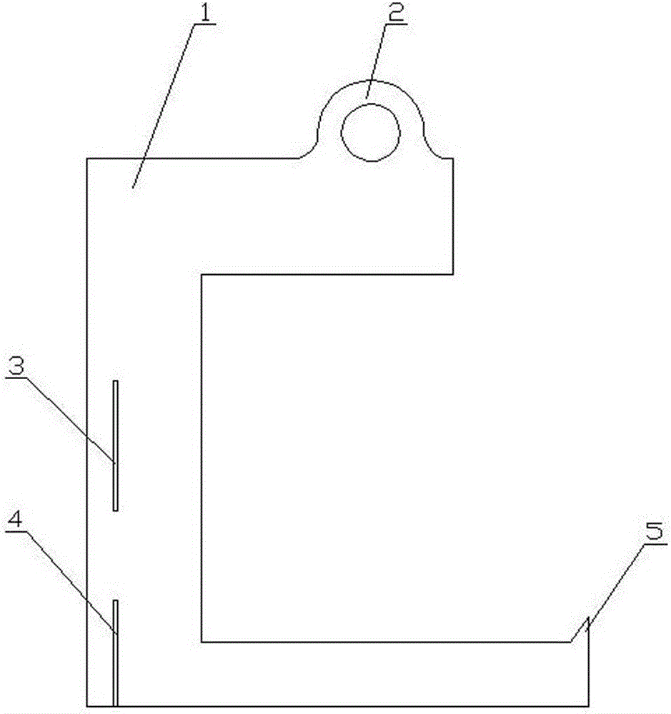
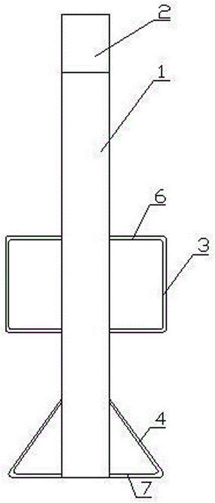
[0013] Such as figure 1 with figure 2 As shown, a C-shaped hook for lifting steel coils of the present invention includes a C-shaped hook body 1 made of steel. A lifting lug 2 is provided on the top of the hook body 1. Handrails are fixed at the middle of both sides of the hook body 1. The handrail includes a vertical rod 3 and two horizontal rods 6. The two ends of the vertical rod 3 are respectively connected to one end of a horizontal rod 6, and the other ends of the two horizontal rods 6 are respectively fixed on the hook body 1. Both sides of the hook body 1 have uprights at the bottom. The uprights include an inclined rod 4 and a horizontal rod 7. The upper end of the inclined rod 4 is fixed on the hook body 1, one end of the horizontal rod 7 and the lower end of the inclined rod 4 The other end is fixed at the lower part of one side of the hook body 1...


PUM


Abstract

The invention relates to a hook, in particular to a C-shaped hook which is arranged on hoisting equipment and is mainly used for hoisting steel coils. The C-shaped hook comprises a C-shaped hook body; a lifting lug is arranged at the top of the hook body. The C-shaped hook is characterized in that an upward antiskid boss is arranged at the lower side of an open part of the hook body; the cross section of the antiskid boss is in a right angled triangle shape; one surface, corresponding to the antiskid boss, of the inner side of the hook body corresponds to a hypotenuse of the right angled triangle. The C-shaped hook is used for hoisting the steel coils, so that potential safety hazards caused by unhooking of the steel coils can be avoided.

Description

Technical field [0001] The invention relates to a hook, in particular to a C-shaped hook installed on a lifting equipment and mainly used for lifting steel coils. Background technique [0002] It is known in the manufacturing industry that the C-hook is a spreader mainly used for lifting steel coils. At present, the C-shaped hook used in the manufacturing industry includes a C-shaped hook body with lifting lugs on the top of the hook body. When installing, fix the lifting lugs and the lifting rope of the lifting equipment together. When working, first control the lifting equipment to lower the sling so that the C-hook is lowered to the position of the center hole of the steel coil to be lifted; then, adjust the direction of the C-hook hook body so that the opening of the hook body faces the steel coil; , Push the C-shaped hook toward the steel coil, so that the lower side of the hook body opening of the C-shaped hook body passes through the center hole of the steel coil, and th...

Claims


Application Information

Patent Timeline
Patent Type & Authority Applications(China)
IPC IPC(8): B66C1/24
CPCB66C1/24
Inventor 丁子怡
Owner 江苏高尔德汽车钢管有限公司
Why Eureka
Eureka Blog
Learn More