Film hanging device
A film and glue rod technology, applied in the field of rubber product processing equipment, can solve the problems of unfavorable film hanging on the glue rod, unreasonable structure design, poor film cooling effect, etc. The effect of neatness
- Summary
- Abstract
- Description
- Claims
- Application Information
AI Technical Summary
Problems solved by technology
Method used
Image

Examples
Embodiment 1
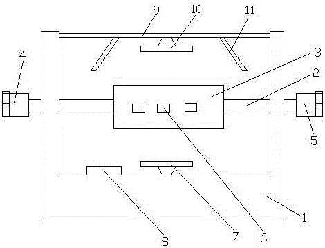
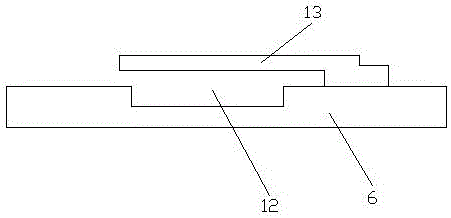
[0033] A film gluing device, comprising a support 1, a cross bar 2 is arranged on the support 1, a roller 3 is nested on the cross bar 2, a first motor 4 is arranged on a side wall of the support 1, the support The other side wall of the seat 1 is provided with a second motor 5, one end of the cross bar 2 penetrates the side wall of the support 1 and is connected to the first motor 4, and the other end of the cross bar 2 penetrates the side wall of the support 1 and connects with the first motor 4. The second motor 5 is connected, and there are many glue hanging rods 6 distributed on the drum 3, the distance between any two glue hanging rods 6 is the same, and the bottom wall of the support 1 is provided with a lower fan 7 and a power supply 8, so The top of the drum 3 is provided with a support rod 9, the support rod 9 is connected to the side wall of the support 1, the upper fan 10 is arranged on the support rod 9, and the upper fan 10 and the lower fan 7 are respectively con...
Embodiment 2
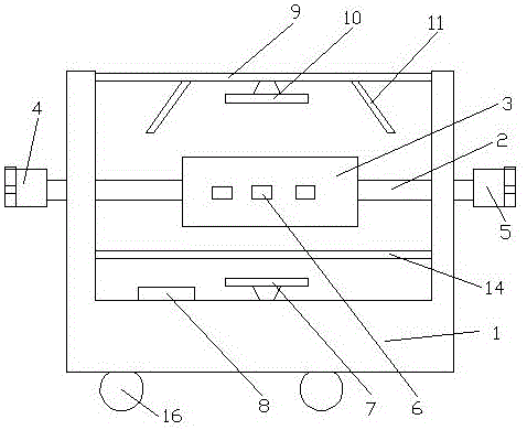
[0036] A film gluing device, comprising a support 1, a cross bar 2 is arranged on the support 1, a roller 3 is nested on the cross bar 2, a first motor 4 is arranged on a side wall of the support 1, the support The other side wall of the seat 1 is provided with a second motor 5, one end of the cross bar 2 penetrates the side wall of the support 1 and is connected to the first motor 4, and the other end of the cross bar 2 penetrates the side wall of the support 1 and connects with the first motor 4. The second motor 5 is connected, and there are many glue hanging rods 6 distributed on the drum 3, the distance between any two glue hanging rods 6 is the same, and the bottom wall of the support 1 is provided with a lower fan 7 and a power supply 8, so The top of the drum 3 is provided with a support rod 9, the support rod 9 is connected to the side wall of the support 1, the upper fan 10 is arranged on the support rod 9, and the upper fan 10 and the lower fan 7 are respectively con...
Embodiment 3
[0040] A film gluing device, comprising a support 1, a cross bar 2 is arranged on the support 1, a roller 3 is nested on the cross bar 2, a first motor 4 is arranged on a side wall of the support 1, the support The other side wall of the seat 1 is provided with a second motor 5, one end of the cross bar 2 penetrates the side wall of the support 1 and is connected to the first motor 4, and the other end of the cross bar 2 penetrates the side wall of the support 1 and connects with the first motor 4. The second motor 5 is connected, and there are many glue hanging rods 6 distributed on the drum 3, the distance between any two glue hanging rods 6 is the same, and the bottom wall of the support 1 is provided with a lower fan 7 and a power supply 8, so The top of the drum 3 is provided with a support rod 9, the support rod 9 is connected to the side wall of the support 1, the upper fan 10 is arranged on the support rod 9, and the upper fan 10 and the lower fan 7 are respectively con...
PUM
 Abstract
Description
Claims
Application Information
 - R&D Engineer
- R&D Manager
- IP Professional
- Industry Leading Data Capabilities
- Powerful AI technology
- Patent DNA Extraction
Browse by: Latest US Patents, China's latest patents, Technical Efficacy Thesaurus, Application Domain, Technology Topic.
© 2024 PatSnap. All rights reserved.Legal|Privacy policy|Modern Slavery Act Transparency Statement|Sitemap