
Industrial detonator packing manipulator

A technology of manipulators and detonators, which is applied in the field of industrial detonator boxing manipulators, can solve problems such as backward technical equipment, low production efficiency, and potential safety hazards, and achieve the effects of improving production safety, improving production efficiency, and simple structure

Inactive Publication Date: 2016-11-23
SICHUAN MIANYANG SOUTHWEST AUTOMATION INST
View PDF7 Cites 9 Cited by
  • Summary
  • Abstract
  • Description
  • Claims
  • Application Information

AI Technical Summary

Problems solved by technology

[0002] In recent years, with the structural adjustment and technological progress of the civil explosive industry, the production process level of industrial detonators has been greatly improved, and production management measures have also been continuously strengthened; however, due to relatively backward technical equipment, many manufacturers still use pure handwork. Or manual operation of simple stand-alone production, which cannot effectively guarantee the safety of personnel, and the production efficiency is not high; production enterprises have an urgent demand for industry-specific automation equipment that can replace manual operations
[0003] At present, the boxing process of domestic industrial detonators is mainly done by hand. Since industrial detonators are pyrotechnic products and are relatively sensitive, the current production mode fails to isolate the operator from the source of danger. There are potential safety hazards and the production efficiency is not high.

Method used


Image

  • Industrial detonator packing manipulator
  • Industrial detonator packing manipulator

Examples


Embodiment

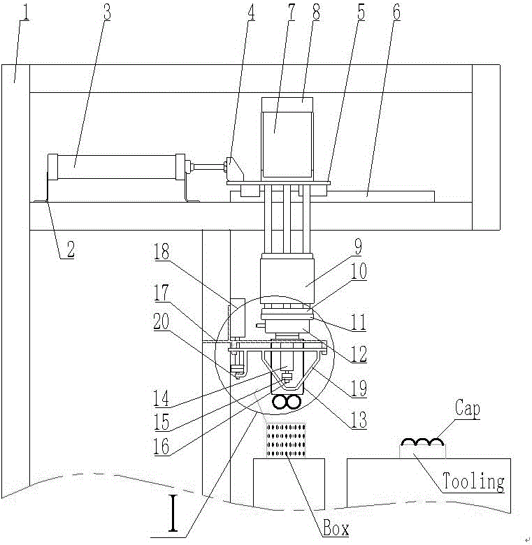
[0015] figure 1 It is the front view of the overall structure of the present invention, figure 2 It is the left view of the overall structure of the present invention

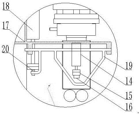
[0016] exist figure 1 - figure 2 Among them, the industrial detonator boxing manipulator of the present invention includes a frame 1, a horizontal cylinder support 2, a horizontal cylinder 3, a push plate 4, a lateral moving plate 5, a slide rail 6, a lifting cylinder A bracket 7, a lifting cylinder A8, and a lifting cylinder B bracket 9, lift cylinder B10, swing cylinder mounting plate 11, swing cylinder 12, magnet box 13, magnet lift cylinder 14, magnet mounting plate 15, magnet 16, shift fork bracket 17, leaf tongue cylinder 18, shift fork 19, The shift fork opening and closing plate 20, its connection relationship is that the horizontal cylinder support 2, the slide rail 6, and the shift fork support 17 are fixed on the frame 1, the horizontal cylinder 3 is installed on the horizontal cylinder support ...


PUM


Abstract

The invention provides an industrial detonator boxing manipulator. The horizontal cylinder bracket, slide rail and shift fork bracket in the mechanism are fixed on the frame, the horizontal cylinder is installed on the horizontal cylinder bracket, and the horizontal moving plate is driven by a push plate along the The slide rail moves, the lifting cylinder A bracket is installed on the lateral moving plate, the lifting cylinder A is installed on the lifting cylinder A bracket, and its front end is connected with the lifting cylinder B bracket, and the lifting cylinder B is installed on the lifting cylinder B bracket, and its front end is passed through the pendulum. The cylinder mounting plate is connected with the swing cylinder to realize the lifting and rotation of the detonator; the upper end of the magnet box is connected with the swing cylinder, and the magnet lifting cylinder is installed in the magnet box, and is connected with the magnet through the magnet mounting plate to realize the grasping of the detonator; The air cylinder is installed on the shift fork bracket, the front end of which is installed with a shift fork opening plate, the upper end of the shift fork is installed on the shift fork support, and the lower end is placed in the sliding groove on the shift fork opening plate, so as to realize the expansion of the tongue of the carton and facilitate the installation. box.

Description

technical field [0001] The invention belongs to the technical field of civil high-risk production, and in particular relates to an industrial detonator box-packing manipulator. Background technique [0002] In recent years, with the structural adjustment and technological progress of the civil explosive industry, the production process level of industrial detonators has been greatly improved, and production management measures have also been continuously strengthened; however, due to relatively backward technical equipment, many manufacturers still use pure handwork. Or manual operation of simple stand-alone production, which cannot effectively guarantee the safety of personnel, and the production efficiency is not high; production enterprises have an urgent demand for industry-specific automation equipment that can replace manual operations. [0003] At present, the boxing process of domestic industrial detonators is mainly carried out by hand. Since industrial detonators a...

Claims


Application Information

Patent Timeline
IPC IPC(8): B25J9/04B25J9/14B25J15/06B65B35/18
CPCB25J9/048B25J9/144B25J9/146B25J15/0608B65B35/18
Inventor 李昂钟顺金谢勇吴斌胡翔黄仁富
Owner SICHUAN MIANYANG SOUTHWEST AUTOMATION INST
Learn More