Cloud point feeding device

A feeding device and fog point technology, which is applied in metal processing, metal processing equipment, manufacturing tools, etc., can solve the problems of unqualified products, feeding, and small fog points, and achieve smooth feeding, simple structure, Easy-to-use effects

Inactive Publication Date: 2016-11-23
ZHONGSHAN MEIJIESHI PACKAGING PROD
View PDF7 Cites 2 Cited by
  • Summary
  • Abstract
  • Description
  • Claims
  • Application Information

AI Technical Summary

Problems solved by technology

[0002] Due to the small size of the fog points used in the spray valve, it is generally impossible to use the feeding spinner mechanism for feeding. The existing practice is to integrate the fog points into a row in the same direction, and they need to be separated one by one when using. This requires design Only the corresponding specific equipment can separate the entire row of fog spots one by one, and the outer wall of the separated fog spots often has defects such as burrs, which can easily lead to unqualified products after assembly

Method used


Image

  • Cloud point feeding device
  • Cloud point feeding device
  • Cloud point feeding device

Examples


Embodiment Construction

[0024] The present invention will be further described below in conjunction with accompanying drawing description and specific embodiment:

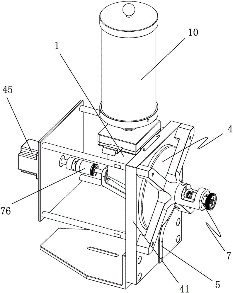
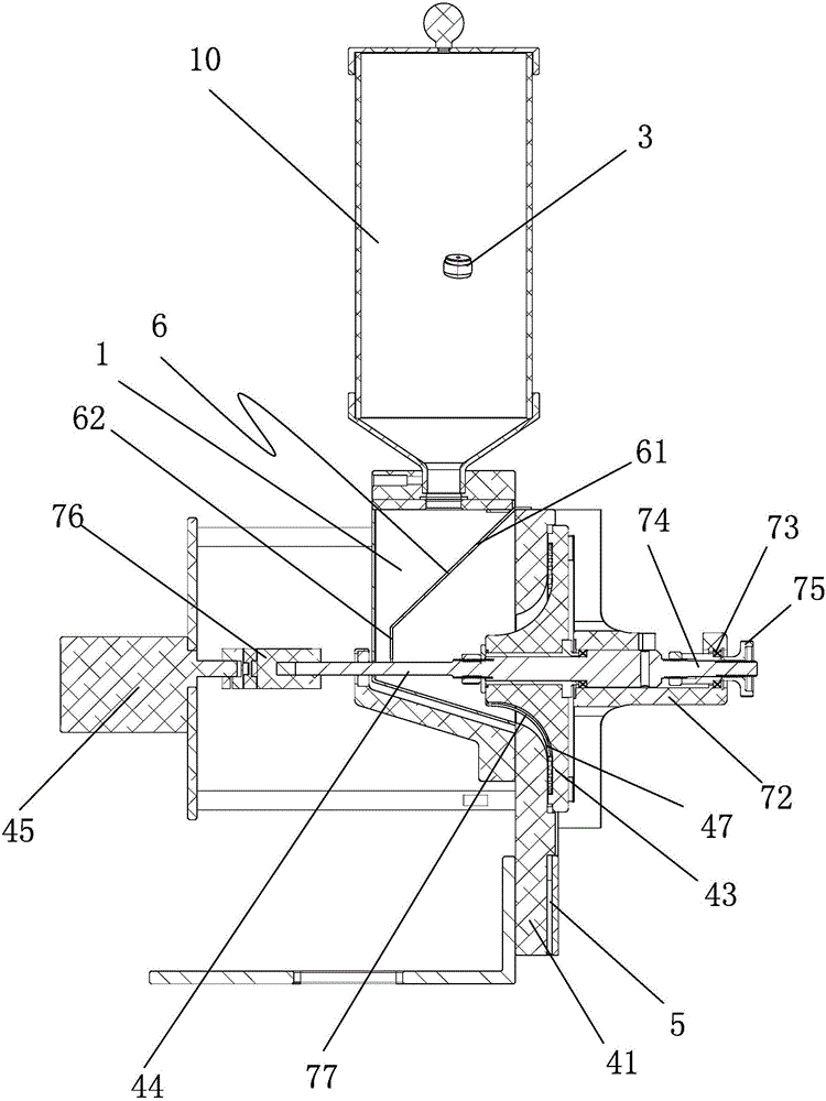
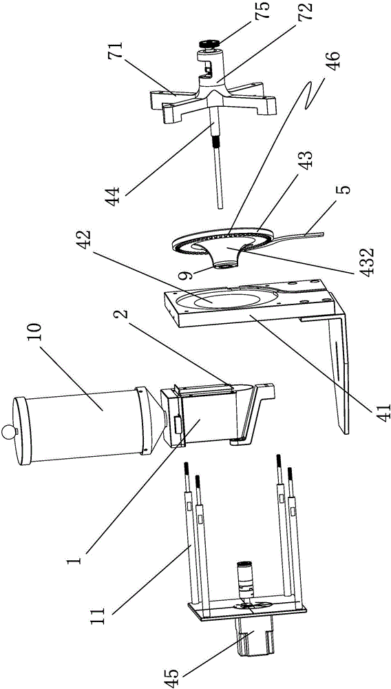
[0025] Such as Figures 1 to 4 The shown fog point feeding device includes a feeding hopper 1, and a connecting slot 2 communicating with the inner cavity of the feeding hopper 1 is provided on one side of the feeding hopper 1, and a connecting slot 2 is provided in the connecting slot 2. There is a material distribution and discharge turntable assembly 4 that enables the fog point 3 to enter and output in a predetermined direction, and a discharge rail 5 that communicates with the distribution and discharge turntable assembly 4 is connected to the supply hopper 1 .

[0026] In the present invention, the distributing and discharging turntable assembly 4 includes a fixed plate 41, on which a mounting slot 42 is arranged, and a rotating disc 43 is arranged in the installing slot 42, and the rotating disc 43 Sleeved on the rotating shaft 44...


PUM


Abstract

The invention discloses a fog point feeding device, which is characterized in that: it comprises a feeding hopper, a connecting slot hole communicating with the inner cavity of the feeding hopper is arranged on one side of the feeding hopper, and a connecting slot hole is arranged in the connecting slot hole. There is a material-distributing and discharging turntable assembly that enables the fog points to enter and output in a predetermined direction, and a discharge rail that communicates with the material-distributing and discharging turntable assembly is connected to the hopper. The purpose of the present invention is to overcome the deficiencies in the prior art, and to provide a fog point feeding device with a simple structure and capable of directional feeding of fog points.

Description

technical field [0001] The invention relates to a fog point feeding device. Background technique [0002] Due to the small size of the fog points used in the spray valve, it is generally impossible to use the feeding spinner mechanism for feeding. The existing practice is to integrate the fog points into a row in the same direction, and they need to be separated one by one when using. This requires design Only the corresponding specific equipment can separate the entire row of fog dots one by one, and the outer wall of the separated fog dots often has defects such as burrs, which can easily lead to substandard products after assembly. Contents of the invention [0003] The purpose of the present invention is to overcome the disadvantages of the prior art, and provide a fog point feeding device with a simple structure and capable of directional feeding of the fog point. [0004] In order to achieve the above object, the present invention adopts the following scheme: [00...

Claims


Application Information

Patent Timeline
IPC IPC(8): B23P19/00
CPCB23P19/001
Inventor 马文超
Owner ZHONGSHAN MEIJIESHI PACKAGING PROD
Why Eureka
Try Eureka