
Ultra-low bed

An ultra-low bed and bed technology, applied in the field of ultra-low beds, can solve the problems of easy shaking of the bed, insufficient safety, high failure rate, etc., and achieve the effect of stable turning process and long service life

Active Publication Date: 2016-11-23
ZHEJIANG JIECHANG LINEAR MOTION TECH +1
View PDF5 Cites 7 Cited by
  • Summary
  • Abstract
  • Description
  • Claims
  • Application Information

AI Technical Summary

Problems solved by technology

[0003] At present, in the field of medical equipment, many nursing beds or nursing beds have appeared. Considering the special needs of patients, the backboard, seat board, thigh board and calf board of the bed are sequentially hinged from front to back, and the back board, thigh board and The calf board can be turned over by the motor or the combination of the motor and the connecting rod, so as to adjust the sleeping position. In addition, in order to facilitate the user to get on and off the bed, the head and tail of the bed are connected to the headboard, and the headboard is designed to be liftable However, the current nursing beds or nursing beds on the market have complex mechanisms for driving the backboard, waist board, thigh board and calf board to turn over, and the stability of the bedside frame is not good when it is lifted or lowered, especially when the turning and lifting actions are carried out at the same time. The whole bed is easy to shake, not safe enough, and the failure rate is relatively high

Method used


Image

  • Ultra-low bed
  • Ultra-low bed
  • Ultra-low bed

Examples


Embodiment 1

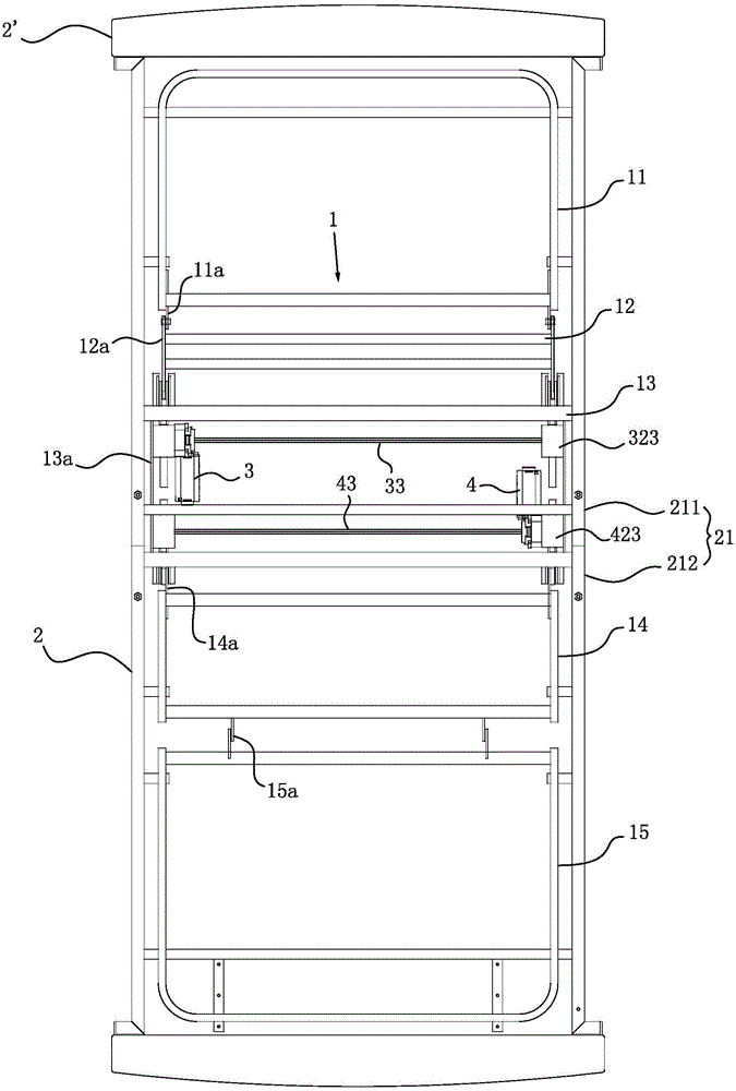
[0045] Such as Figure 1 to Figure 7 As shown, a kind of ultra-low bed, comprises bed and is positioned at bed head and the headstock 2 ' of rear part, and bed comprises bed 1 and is used to support bed frame 2 of bed 1, and the present embodiment The bedside frame 2' is liftable, and its overall height is variable. In this embodiment, the bedside frame 2' is connected with the bed frame, and drives the bed to go up and down when lifting.

[0046] The bed body 1 of this embodiment comprises a back frame 11, a waist frame 12, a seat frame 13, a thigh frame 14 and a calf frame 15 which are hinged sequentially from front to back, and the back frame 11, waist frame 12, seat frame 13, thigh frame 14 and The upper part of the calf frame 15 is respectively equipped with a bed board or covered with a soft material. When the user uses it, a mat or a cushion can also be added on this basis to improve the comfort of use. The seat frame 13 is fixed on the bed frame 2, and the bed frame 2 ...

Embodiment 2

[0058] Such as Figure 8 to Figure 11 As shown, the difference between this embodiment and Embodiment 1 is that there is no need to set a third connecting rod, the first connecting rod 3a has a first force-receiving part 3a', and the first force-receiving part 3a' is the first connecting rod 3a, the first force-receiving part 3a' is located on the telescopic movement path of the driving end 3' of the first driver 3, and when the driving end 3' of the first driver 3 moves telescopically, the force acts directly on the first force-receiving part 3a' Drive the first connecting rod 3a to swing.

[0059] It should be noted that the above structural changes in this embodiment may also be applicable to other embodiments of the present invention.

Embodiment 3

[0061] Such as Figure 12 and Figure 13 As shown, the difference between this embodiment and Embodiment 1 is that the second connecting rod 3b is provided with a strip-shaped guide hole 3b', and the bed frame 2 is provided with a guide post 22 extending into the guide hole 3b' and a support The guide plate 23 is arranged below the second connecting rod 3b and parallel to the guide hole. The second connecting rod 3b can slide along the length direction of the guide hole and the guide plate. 11a', one end of the second link 3b is located on the swing path of the first link 3a, and the back frame force receiving part 11a' is located on the sliding path of the other end of the second link 3a.


PUM


Abstract

The invention discloses an ultra-low bed, and belongs to the technical field of medical apparatus and instruments. According to the technical scheme, the ultra-low bed mainly comprises a bed and bedside frameworks positioned on the head and the tail of the bed, wherein the bed comprises a bed body and a bed frame for supporting the bed body; the bedside frameworks are connected with the bed frame; the bed body comprises a back frame, a waist frame, a seat frame, a thigh frame and a shank frame which are successively hinged to one another from front to back; the seat frame is fixed on the bed frame; the bed frame is provided with a first driver and a second driver which are provided with driving ends; the bed frame is hinged to a first connecting rod; a second connecting rod is arranged between the first connecting rod and the back frame; the driving end of the first driver carries out stretching motion to drive the first connecting rod to swing; one end of the second connecting rod is in linkage with the first connecting rod; the other end of the second connecting rod applies a force which enables the back frame to overturn vertically relative to the waist frame to the back frame; a hinge pin which is located in a swinging region of the first connecting rod is arranged on the waist frame; and the first connecting rod can applies a force which enables the waist frame to overturn vertically relative to the seat frame to the waist frame through the hinge pin. The ultra-low bed has the advantages of high stability and safety and long service life.

Description

technical field [0001] The invention belongs to the technical field of medical devices and relates to an ultra-low bed. Background technique [0002] Calculated based on normal work and rest, people need about one-third of sleep time every day, and the comfort of the bed determines the quality of sleep to a large extent. Especially for bedridden old people, disabled people or patients, if they lie flat or on their sides for a long time, local pressure will be caused, resulting in many health problems. [0003] At present, in the field of medical equipment, many nursing beds or nursing beds have appeared. Considering the special needs of patients, the backboard, seat board, thigh board and calf board of the bed are sequentially hinged from front to back, and the back board, thigh board and The calf board can be turned over by the motor or the combination of the motor and the connecting rod, so as to adjust the sleeping position. In addition, in order to facilitate the user t...

Claims


Application Information

Patent Timeline
IPC IPC(8): A61G7/015A61G7/012A61G7/05A61G7/057
CPCA61G7/001A61G7/012A61G7/015A61G7/05A61G2203/10A61G2203/70
Inventor 李路平覃鸿陆柯军黄春峰
Owner ZHEJIANG JIECHANG LINEAR MOTION TECH
Learn More