
Control method for shooting equipment and shooting equipment

A technology for shooting equipment and control units, which is applied to parts of color TVs, parts of TV systems, TVs, etc., can solve problems such as complicated operations and poor shooting effects, optimize shooting effects, reduce operational complexity, and improve The effect of user experience and favorability

Active Publication Date: 2016-11-16
NINEBOT (BEIJING) TECH CO LTD
View PDF5 Cites 16 Cited by
  • Summary
  • Abstract
  • Description
  • Claims
  • Application Information

AI Technical Summary

Problems solved by technology

[0004] Embodiments of the present invention provide a method for controlling a photographing device and a photographing device, so as to at least solve the technical problems that the photographing device in the prior art needs to be operated manually, the operation is complicated and the photographing effect is poor

Method used


Image

  • Control method for shooting equipment and shooting equipment
  • Control method for shooting equipment and shooting equipment
  • Control method for shooting equipment and shooting equipment

Examples


Embodiment 1

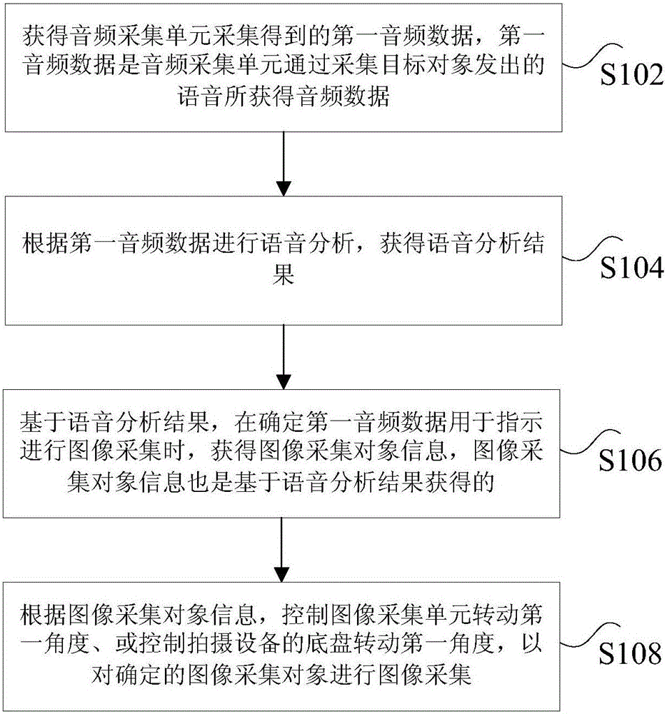
[0020] According to an embodiment of the present invention, a method embodiment of a method for controlling a shooting device is provided. It should be noted that the steps shown in the flow chart of the accompanying drawings can be executed in a computer system such as a set of computer-executable instructions, Also, although a logical order is shown in the flowcharts, in some cases the steps shown or described may be performed in an order different from that shown or described herein.

[0021] Wherein, the control method of the shooting device is applied to the shooting device, and the shooting device may have an audio collection unit and an image collection unit, which can collect sounds and images around the shooting device to obtain audio data and image data.

[0022] figure 1 is a flow chart of a method for controlling a photographing device according to an embodiment of the present invention, such as figure 1 As shown, the method includes the following steps:

[0023]...

Embodiment 2

[0095] According to an embodiment of the present invention, an embodiment of a photographing device is also provided.

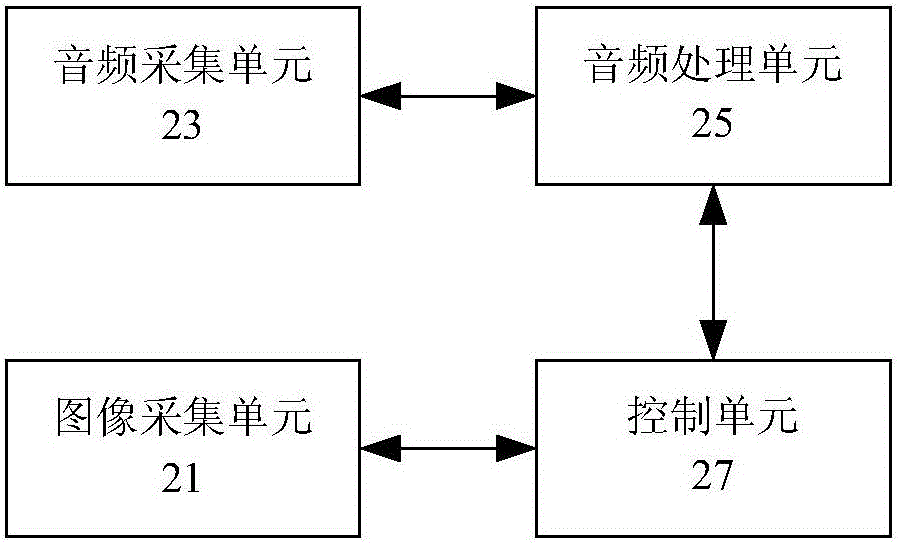
[0096] figure 2 is a schematic diagram of a shooting device according to an embodiment of the present invention, such as figure 2 As shown, the shooting equipment includes:

[0097] The image acquisition unit 21 is configured to acquire image data.

[0098] Specifically, the above-mentioned image acquisition unit 21 may be a device with a shooting function, such as a camera, a camera, or a video recorder.

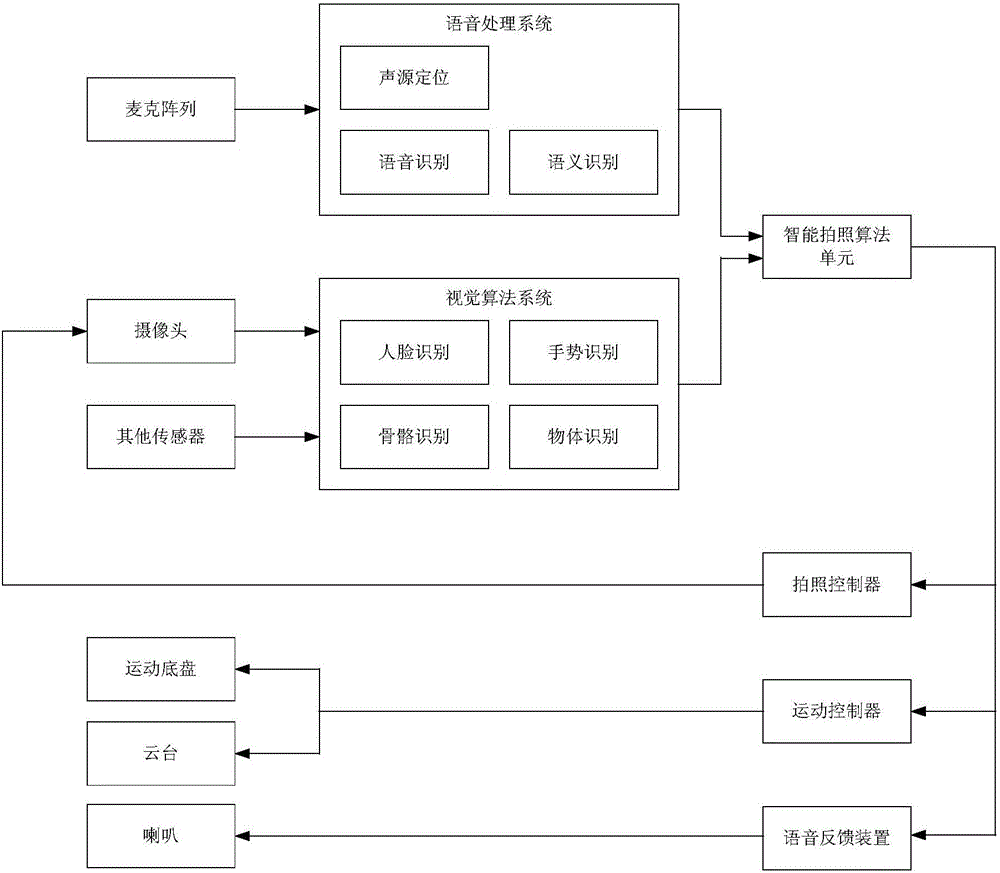
[0099] In an alternative, such as image 3As shown, the photographing device may be a smart device with a photographing function, such as an intelligent robot, and the photographing device may include a camera. The photographing device can collect image data within the photographing range of the camera through the camera, so that image collection can be performed.

[0100] The audio collection unit 23 is configured to obtain the first audio data by ...


PUM


Abstract

The invention discloses a control method for shooting equipment and the shooting equipment. The control method is applied to the shooting equipment, and the shooting equipment comprises an audio acquisition unit and an image acquisition unit; the control method comprises the steps of acquiring first audio data acquired by the audio acquisition unit; performing speech analysis according to the first audio data, and acquiring a speech analysis result; based on the speech analysis result, acquiring image acquisition object information when determining that the first audio data are used for indicating to perform image acquisition; and according to the image acquisition object information, controlling the image acquisition unit to rotate for a first angle, or controlling a chassis of the shooting equipment to rotate for the first angle, so as to perform image acquisition on a determined image acquisition object. The control method for the shooting equipment provided by the invention solves the technical problems that shooting equipment in the prior art needs manual operation, the operation is complex and the shooting effect is poor.

Description

technical field [0001] The present invention relates to the field of photographing equipment control, in particular to a photographing equipment control method and the photographing equipment. Background technique [0002] With the continuous development of the Internet, more and more users are used to taking photos and uploading them to the Internet, and sharing them with their relatives and friends. However, the existing shooting equipment, such as cameras, video cameras, mobile phones with shooting functions, etc., need to manually adjust the shooting options, the operation process is complicated and cumbersome, and the automatic shooting options of the shooting equipment are not smart enough. Moreover, when the user needs to take a selfie or take a co-shot with others, if there is no help from others, he usually uses a selfie stick to shoot, or uses a tripod, and realizes it through the timing shooting function. However, the shooting effect is often not ideal. [0003]...

Claims


Application Information

Patent Timeline
Patent Type & Authority Applications(China)
IPC IPC(8): H04N5/232G10L15/26
CPCG10L15/26H04N23/60
Inventor 陆见微
Owner NINEBOT (BEIJING) TECH CO LTD
Learn More