Data connection line

A technology of data connection wires and wires, which is applied in the direction of connection, parts of connection devices, electrical components, etc., which can solve problems such as difficult processing, unqualified finished product quality, and prone to defective products

Inactive Publication Date: 2016-11-16
邹海华
View PDF5 Cites 0 Cited by
  • Summary
  • Abstract
  • Description
  • Claims
  • Application Information

AI Technical Summary

Problems solved by technology

[0004] However, the electrode ring a is only positioned by the electrode ring installation part during assembly, and after the electrode ring a is assembled in place, it is necessary to inject molten plastic or gel between each electrode ring a to form the insulating filling layer , because the insulating filling layer needs to have the same outer contour as the electrode ring a, that is, when forming the insulating filling layer, it needs to be molded with a mold, so that the electrode ring a is likely to be displaced when the insulating filling layer is formed, resulting in the quality of the finished product Unqualified; in addition, when the insulating filling layer is formed, it is difficult to avoid part of the liquid raw material covering the outer wall of the electrode ring a. In this way, after the insulating filling layer is formed, it is necessary to insulate the outer wall of the electrode ring a and the electrode ring a. The fill layer is sanded to remove excess insulation
In short, the processing process of this scheme is still relatively difficult, and it is prone to defective products, and there is room for further improvement

Method used


Image

  • Data connection line
  • Data connection line
  • Data connection line

Examples


Embodiment 1

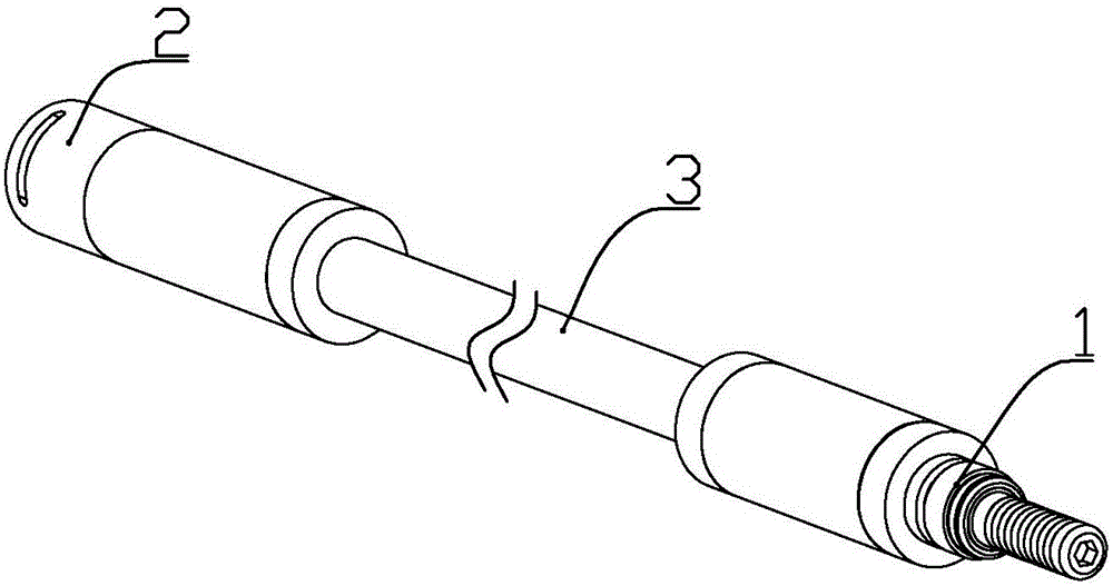
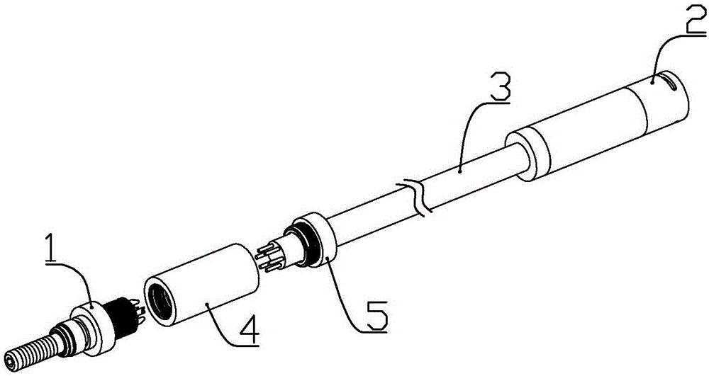
[0058] according to Figure 1 to Figure 24 As shown, this embodiment is a data connection cable, including a wire 3 , a male connector 1 arranged at one end of the wire and a female connector 2 arranged at the other end of the wire.

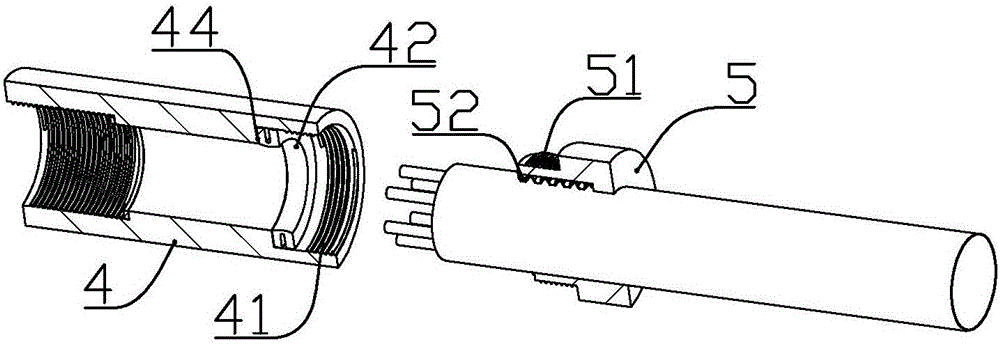
[0059] The position close to the end of the wire 3 is covered with a threaded cable joint 5 and a locking nut 4, the outer wall of one end of the cable joint 5 is formed with an external thread a51, and the inner wall of one end of the locking nut 4 is formed There is an internal thread a41 cooperating with the external thread a51; a rubber ring positioning shoulder 44 is formed in the lock nut 4 adjacent to the internal thread a41, and the rubber ring positioning shoulder 44 is formed inside the lock nut. A U-shaped rubber ring 42 is installed between the end of the cable joint.

[0060] The outer circumference of the U-shaped rubber ring is sealed against the inner wall of the locking nut, and the inner circumference of the U-shaped rubber rin...

Embodiment 2

[0092] In this embodiment, on the basis of Embodiment 1, the following improvements are made: the end electrode tip 141 of the end electrode 14 is axially formed with a glue overflow hole that communicates with the glue injection groove on the insulating cylinder, When injecting glue through the glue injection port on the locking piece, the locking piece is facing down, the end electrode head is facing up, the glue flows into the glue injection groove along the glue injection channel, until the glue overflows from the glue overflow through hole Note that the glue injection tanks are all filled with glue, just scrape off the glue on the outer surface of the end electrode head before the glue solidifies.

[0093] In addition, both ends of each electrode ring a are tapered slopes with a high outer circumference and a lower inner circumference, so that the electrode ring a can closely fit with the outer circumference of the adjacent insulating ring without gaps between the two. Af...


PUM


Abstract

The invention discloses a data connection line, which comprises a wire, a male head and a female head, wherein a cable contact and a lock nut in threaded connection sleeve the position, close to the end part, of the wire; the male head comprises a plug housing and an insulating cylinder arranged on the plug housing; the insulating cylinder comprises a cylinder outer pipe and an insulating bracket; a glue injecting groove is formed in the insulating bracket between two adjacent installation parts; the female head comprises a female head shell, an insulating frame connected to the inside of the female head shell, six electrode rings a arranged in the insulating frame, and connecting wires b; and the connecting wires b are arranged in the insulating frame and are welded and fixed to the corresponding electrode rings a. After a locking element is screwed in place, the insulating cylinder and the plug housing are connected into a whole and cannot be disassembled; and after condensed glue is injected into the rear end of the plug housing, a locating nut and the locking element are connected into a whole, so that the condition that the positions of the electrode rings a and insulating rings are kept stable can be ensured.

Description

technical field [0001] The invention belongs to the field of connecting wires, and in particular relates to data connecting wires of communication electrical equipment. Background technique [0002] The Chinese patent application with document number 201610028956.1 discloses a data connection line, including a socket and a plug connector, and the plug connector includes a plug shell and an insulating cylinder installed on the plug shell, and the insulator Two or more electrode rings a are embedded equidistantly in the axial direction on the outer wall of the front part of the cylinder, and the same number of connecting wires a as the electrode rings are embedded in the insulating cylinder along the axial direction. The insulating cylinder includes an insulating support for positioning the electrode ring a and inserting the connecting wire a, and an insulating support for filling the gap between adjacent electrode rings a after the electrode ring a and the connecting wire a a...

Claims


Application Information

Patent Timeline
Patent Type & Authority Applications(China)
IPC IPC(8): H01R31/06H01R13/502H01R13/405
CPCH01R31/06H01R13/405H01R13/502
Inventor 邹海华
Owner 邹海华
Why Eureka
Try Eureka