
Driving structure of single-shaft shredding machine

A driving structure, shredder technology, applied in mechanical equipment, transmission parts, grain processing and other directions, can solve the problems affecting the service life, the vibration of the knife roller, affecting the processing effect and service life of the knife roller, etc., so as to improve the service life. , The effect of improving processing quality and service life

Inactive Publication Date: 2016-11-16
GENOX RECYCLING TECH
View PDF5 Cites 0 Cited by
  • Summary
  • Abstract
  • Description
  • Claims
  • Application Information

AI Technical Summary

Problems solved by technology

Existing motors and reducers are generally installed directly outside the single-shaft shredder box without protection on the outside, so fine dust or materials leaking from the box can easily enter the motor and reducer, affecting the service life; moreover, The reducer will generate a large vibration when it is working, which will drive the vibration of the cutter roller and affect the processing effect and service life of the cutter roller

Method used


Image

  • Driving structure of single-shaft shredding machine
  • Driving structure of single-shaft shredding machine
  • Driving structure of single-shaft shredding machine

Examples


Embodiment Construction

[0023] Below, in conjunction with accompanying drawing and specific embodiment, the present invention is described further:

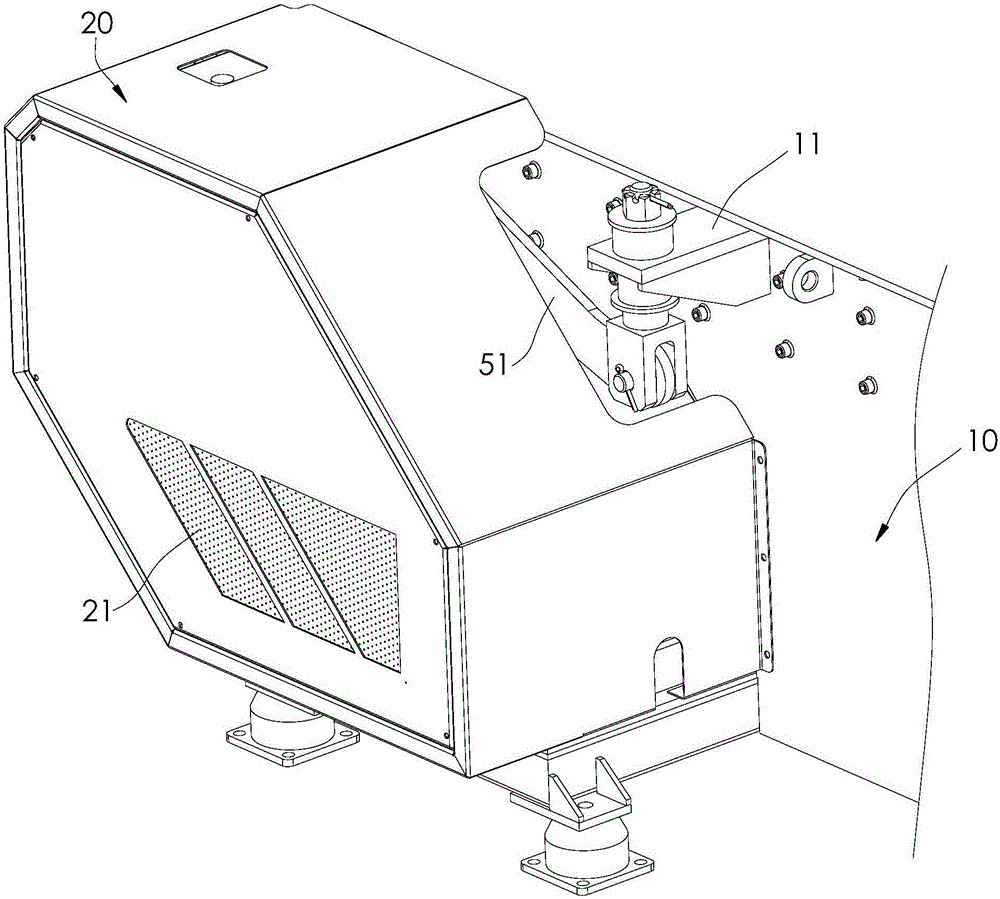
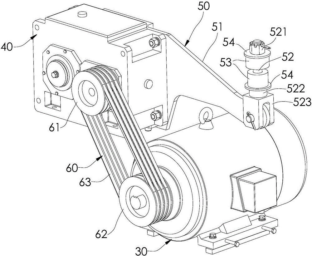
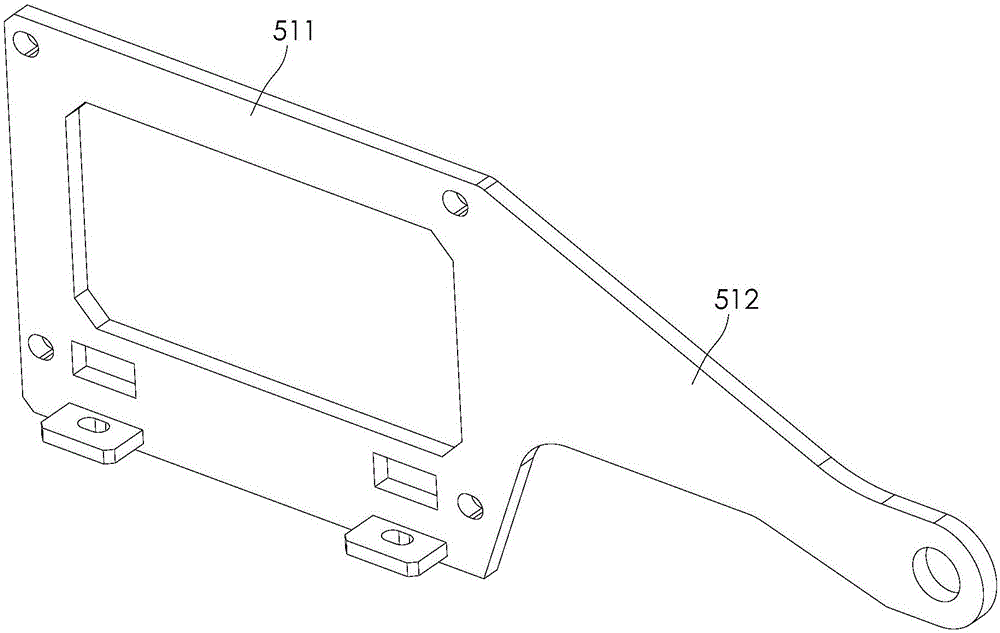
[0024] Such as Figure 1 to Figure 3 As shown, the driving structure of the single-shaft shredder of the present invention includes a box body 10 , a protective cover 20 , a motor 30 , a reducer 40 and a shock-absorbing mechanism 50 . One side of the box body 10 is fixed with a mounting plate 11; the protective cover 20 is fixed on one side of the box body 10; the motor 30 is installed on one side of the box body 10 and is located inside the protective cover 20; the reducer 40 is installed on the box body 10- Side and located inside the protective cover 20, the input end of the reducer 40 is connected with the rotating shaft of the motor 30, and the output shaft of the reducer 40 is fixedly connected with the main shaft of the knife roller; the shock absorbing mechanism 50 includes a shock absorbing arm 51, a movable rod 52 and two elastic parts 53, th...


PUM


Abstract

The invention discloses a driving structure of a single-shaft shredding machine. The driving structure comprises a box body, a protective cover, a motor, a speed reducer and a vibration reducing mechanism. A mounting plate is fixed on one side of the box body; the protective cover is fixed on one side of the box bod; the motor is mounted on one side of the box body, and is positioned in the protective cover; the speed reducer is mounted on one side of the box body, and is positioned in the protective cover; an input end of the speed reducer is in transmission connection with a rotating shaft of the motor; an output shaft of the speed reducer is fixedly connected with a main shaft of a cutter roller; the vibration reducing mechanism includes a vibration reducing arm, a movable rod and two elastic pieces; the movable rod is inserted in the mounting plate; one end of the vibration reducing arm is fixed with a shell of the speed reducer, and the other end of the vibration reducing arm is hinged to the lower end of the movable rod; two limiting pieces are arranged on the movable rod, and are respectively positioned above and below the mounting plate; and each elastic piece is clamped between the mounting plate and the limiting pieces. The driving structure can protect the motor and the speed reducer, and reduces vibration of the speed reducer.

Description

technical field [0001] The invention relates to a driving structure of a single-shaft shredder. Background technique [0002] A single-shaft shredder refers to a shredder with a single knife roller. A motor is installed on the single-shaft shredder, and the motor drives the knife roller to rotate through a reducer. Existing motors and reducers are generally installed directly outside the single-shaft shredder box without protection on the outside, so fine dust or materials leaking from the box can easily enter the motor and reducer, affecting the service life; moreover, When the reducer is working, it will generate a large vibration, which will drive the vibration of the cutter roller and affect the processing effect and service life of the cutter roller. Contents of the invention [0003] In order to overcome the deficiencies of the prior art, the object of the present invention is to provide a driving structure of a single-shaft shredder, which can protect the motor and...

Claims


Application Information

Patent Timeline
IPC IPC(8): F16H57/028F16H57/029B02C18/24B02C18/16
CPCF16H57/028B02C18/16B02C18/24F16H57/029
Inventor 蒋经发
Owner GENOX RECYCLING TECH
Learn More