
Wind gathering power generation equipment

A power generation equipment and wind gathering technology, which is applied in wind power generation, mechanical equipment, wind engines, etc., can solve the problems of small wind energy capture and low utilization rate, and achieve the effect of improving utilization rate, efficient utilization, and expanding wind capture area

Active Publication Date: 2016-11-16
CHUANGKEBANG (SHANDONG) TECH SERVICE CO LTD
View PDF5 Cites 3 Cited by
  • Summary
  • Abstract
  • Description
  • Claims
  • Application Information

AI Technical Summary

Problems solved by technology

[0004] The purpose of the present invention is to overcome the defects of the flat-axis fan or the vertical-axis fan and the existing wind-gathering power generation device with less wind energy capture and low utilization rate, and provide a wind-gathering power generation device that can capture wind energy to the greatest extent and improve the utilization rate of wind energy

Method used


Image

  • Wind gathering power generation equipment
  • Wind gathering power generation equipment

Examples


Embodiment Construction

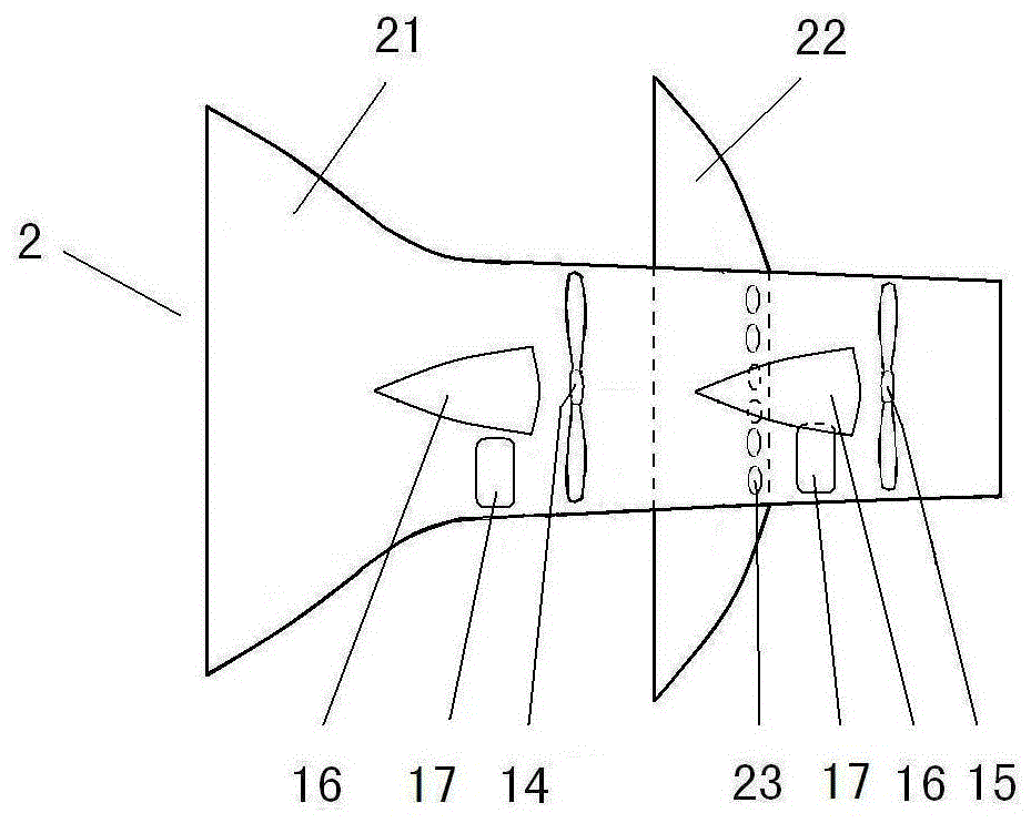
[0012] figure 1 Among them, the first air gathering tube 2 is provided with two first bell mouths 21 and second bell mouths 22 facing the same direction, one end of the first air gathering tube 2 is provided with the first bell mouth 21, and the middle position is provided with the second bell mouth 22. The root of the second bell mouth 22 is provided with a hole 23 obliquely pierced from the outer wall of the air collecting tube to the inner wall as the air inlet channel, and the first fan 14 and the second fan 15 are arranged before and after the hole 23 . After the air intake of the first bell mouth 21 makes the first fan 14 rotate to generate electricity, the wind energy margin will not be lost and wasted due to the sealing of the cylinder, and the air intake that can be imported into the hole 23 of the second bell mouth 22 makes the second fan 15 Turn to generate electricity.

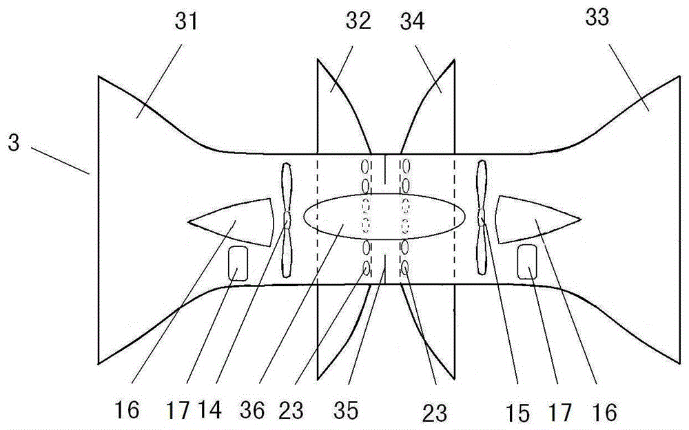
[0013] Or establish the second air gathering tube 3 (see figure 2 ), each of which has two t...


PUM


Abstract

The invention discloses wind gathering power generation equipment. At least two fans are mounted in a wind gathering cylinder; the fans are correspondingly provided with intake ways; wind is fed from horn ports to enable wind energy margins of rotating power generation by the fan on the front side to be not dispersed and wasted due to the sealed cylinder; the wind gathered in the other intake way enables the fan on the back side to rotate for power generation; and the collected wind energy is higher in utilization rate compared with a flat axis fan or a vertical axis fan or traditional wind gathering power generation devices. The wind gathering cylinders are fixed on a frame structure in a parallel or overlap manner to form a wind power dam; and all wind energy in the wind power dam area can be captured and used, so that the loading capacity and the power generation capacity of a wind field can be improved to the greatest extent.

Description

technical field [0001] The invention relates to wind power generation technical equipment, in particular to wind gathering power generation equipment. Background technique [0002] Existing wind farms are generally equipped with flat-axis fans or vertical-axis fans to generate electricity, and a large distance should be left between adjacent fans, which will waste a lot of wind energy in the wind farm; the wind energy in the swept area of ​​the wind blades cannot be fully utilized, and the Less than half of the captured wind energy is utilized, and the residual wind energy after the wind turbine is utilized is not only basically lost, but also often causes turbulent wind, which affects the use of wind energy by adjacent wind turbines. Therefore, the existing wind farm occupies a large area, but the wind capture area is small, and the utilization rate of wind energy is low; the wind farm construction investment is large, but the installed capacity and power generation are sma...

Claims


Application Information

Patent Timeline
Patent Type & Authority Applications(China)
IPC IPC(8): F03D80/00F03D9/25
CPCF03D1/04F03D3/04Y02E10/72Y02E10/74
Inventor 黄宝文黄郑隽
Owner CHUANGKEBANG (SHANDONG) TECH SERVICE CO LTD
Learn More