Pile cap former, pile head treatment and pile cap construction method

A former and pile cap technology, which is applied in sheet pile walls, foundation structure engineering, construction, etc., can solve problems such as irregular operation of construction personnel, irregular shape of cylindrical soil molds, uncontrollable construction quality, etc. The method is flexible, the construction process is easy to control, and the effect of the construction process is easy to control

Active Publication Date: 2018-03-09
陕西桩鑫建筑科技有限公司 +1
View PDF7 Cites 0 Cited by
  • Summary
  • Abstract
  • Description
  • Claims
  • Application Information

AI Technical Summary

Problems solved by technology

Therefore, the traditional pile head treatment and pile cap construction is carried out after concrete pouring and 28-day curing. At this time, the strength of the concrete has reached 98% to 99% of the design strength. Slow, and excavators, tools and other equipment often collide with the pile head during the processing process. Since the pile head is a brittle rigid body after solidification, it is very easy to break once it collides
In addition, when the artificial cylindrical soil mold 1-4 is used, not only the speed is slow, but also the shape of the cylindrical soil mold 1-4 is irregular
[0004] From the above content, it can be seen that when using the above-mentioned traditional method for pile head treatment and pile cap construction, there are the following main problems: first, low construction efficiency: each person can only construct 3 to 5 pile caps per day; second, high cost : purely manual production, high labor cost; third, the construction quality is uncontrollable: due to the non-standard operation of the construction personnel, the construction quality of the pile cap cannot be effectively guaranteed; fourth, the construction process is complicated and the labor intensity is high; After the body concrete is solidified, the pile cap construction will be carried out, which will affect the construction period of the cast-in-situ pile

Method used


Image

  • Pile cap former, pile head treatment and pile cap construction method
  • Pile cap former, pile head treatment and pile cap construction method
  • Pile cap former, pile head treatment and pile cap construction method

Examples


Embodiment Construction

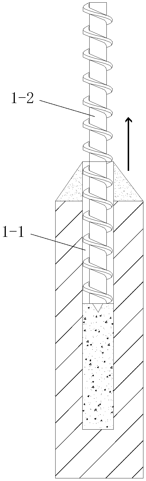
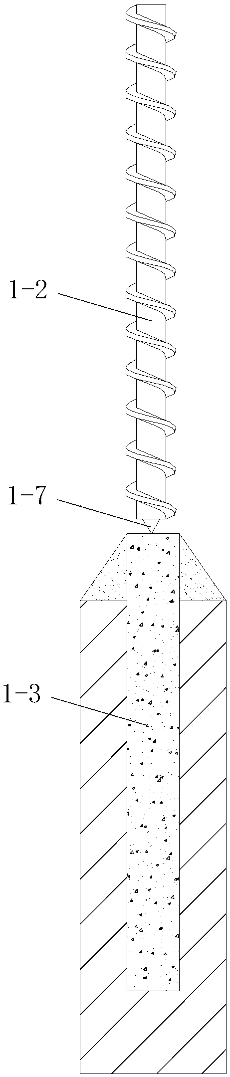
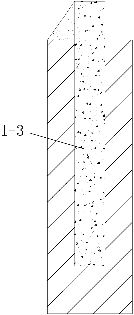
[0066] like figure 1 , figure 2 A pile cap former shown includes a pile cap forming drill bit for hole-forming pile cap 2 to be constructed and a rotary driving device that drives the pile cap forming drill bit to continuously rotate, and the rotary driving device is located at the Above the pile cap forming drill bit, the pile cap forming drill bit is in transmission connection with the rotary drive device; Figure 5 and Image 6 , the pile cap 2 to be constructed comprises an upper pile cap section and a lower pile cap section, the upper pile cap section is a truncated cone, the lower pile cap section is a truncated cone, and the diameter of the lower pile cap section is determined by the upper Decrease gradually to the bottom and the diameter of its upper end is identical with the diameter of described upper pile cap section; The pile cap 2 that needs to be constructed is the pile cap of cast-in-place pile, and the diameter of described cast-in-situ pile is the same as ...


PUM


Abstract

The invention discloses a pile cap forming machine and a pile head treatment and pile cap construction method. The pile cap forming machine comprises a pile cap forming drill bit and a rotary driving device; the rotary driving device is positioned above the pile cap forming drill bit; a pile cap needing to be constructed includes a circular table-shaped upper pile cap section and a conical table-shaped lower pile cap section; the pile cap forming drill bit includes a core pipe, and spiral blades arranged on the outer side wall of the core pipe; the core pipe is divided into an upper section and a lower section; the spiral blades are divided into upper blades and lower blades; the upper section and the upper blades form a cylindrical drill bit; and the lower section and the lower blades form a conical table-shaped drill bit. The pile head treatment and pile cap construction method comprises the steps of: (1) pile heat treatment; (2) forming of a pile cap soil mold by downward drilling of the pile cap forming machine; (3) filling construction of pile cap concrete; and (4) forming of a pile cap. The pile cap forming machine is reasonable in design, convenient for construction and excellent in use effect, can simply and quickly finish the pile cap construction process, is easy to control the construction process, and is high in quality of the pile cap formed by construction.

Description

technical field [0001] The invention belongs to the technical field of pile foundation construction, and in particular relates to a pile cap former, a pile head treatment and a pile cap construction method. Background technique [0002] Nowadays, after cast-in-situ piles are piled, pile cap construction is usually carried out manually, and the pile cap is generally a concrete structure. Such as Figure 1-1 to Figure 1-8 As shown, when the pile cap construction is carried out manually, the construction process mainly includes the following steps: the first step, after the drill hole 1-1 is formed, the drill pipe 1-2 is lifted up and passed through the drill pipe 1-2 to drill the hole 1-1 pouring concrete, see Picture 1-1 In the second step, the drill pipe 1-2 is lifted up to the outside of the borehole 1-1, and after the poured concrete in the borehole 1 is solidified, the cast-in-place pile body 1-3 is obtained. In order to ensure the quality of the pile head, the poured p...

Claims


Application Information

Patent Timeline
Patent Type & Authority Patents(China)
IPC IPC(8): E02D5/72E02D5/34
CPCE02D5/34E02D5/72
Inventor 隋孝民庄金敖文李季宏李彦民庄春
Owner 陕西桩鑫建筑科技有限公司
Why Eureka
Try Eureka