
A signal conditioning method on the secondary side of a mutual induction coil

A technology of signal conditioning and mutual inductance coils, which is applied in the direction of measuring devices, instruments, and measuring electrical variables, etc., can solve the problems of large gaps in precision requirements and increased difficulty, and meet different precision requirements, reduce design difficulty, and follow-up circuit systems stable effect

Inactive Publication Date: 2018-08-28
SHANDONG UNIV OF TECH
View PDF7 Cites 0 Cited by
  • Summary
  • Abstract
  • Description
  • Claims
  • Application Information

AI Technical Summary

Problems solved by technology

[0006] Since the current on the primary side of the mutual inductance coil of the electronic current transformer in the prior art is near the rated value of the normal operation of the power grid for a long time, it only exceeds the rated maximum value of the power grid operation in a short period of time such as a short-circuit fault; The processing method of direct linear conditioning for wide dynamic range signals takes the safety of the power grid as the priority design element, and the linear amplification or reduction of the operating current signal of the power grid to make the dynamic range adapt to the requirements of subsequent circuits must also be protected. The signal is the priority design element; measure the power grid signal whose dynamic range is 20 times of the rated primary current linear relationship. After it is directly linearly adjusted by the existing technology, the subsequent circuit will work in the vicinity of 1 / 20 of its maximum dynamic range for a long time. The dynamic range of the measurement signal is 5% to 120% of the rated primary current, and the accuracy requirements of the two are too different. Obviously, this makes the follow-up circuit on the secondary side of the mutual inductance coil of the electronic current transformer in the sampling accuracy of the measurement signal. Increased difficulty in design and subsequent overall circuit stability design

Method used


Image

  • A signal conditioning method on the secondary side of a mutual induction coil
  • A signal conditioning method on the secondary side of a mutual induction coil

Examples


Embodiment 1

[0037] Embodiment 1: The power supply voltage amplitude of the power supply module is ±5V, and bipolar signal conditioning based on positive and negative dual power supplies:

[0038] In this embodiment, the critical value of the signal protection signal on the secondary side of the mutual induction coil is ±5V, the power supply voltage amplitude of the power supply module is ±5V, the critical value of the signal measurement signal on the secondary side of the mutual induction coil is ±0.5V, and the output signal is bipolar Signal.

[0039] For positive polarity signals, the critical value of the measurement signal is 0.5V, the critical value of the protection signal range is 5V, and the power supply voltage amplitude of the power supply module U gm =5V, the conditioning process is:

[0040] Mutual induction coil secondary side signal U d Signal Threshold for Protection U dm =5V, secondary side signal of mutual induction coil U d Signal threshold for measurement U em...


PUM


Abstract

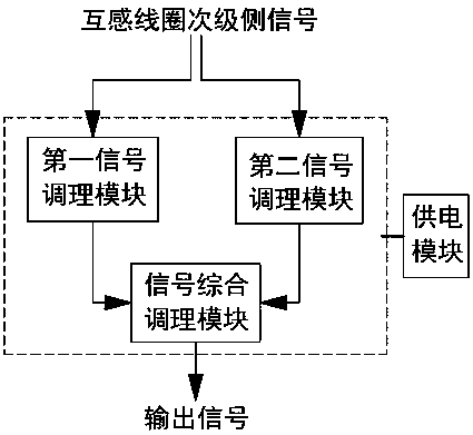
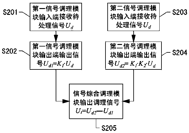
The invention relates to a mutual inductance coil secondary-side signal conditioning device and method, and belongs to the field of electronic current transformer signal processing. The mutual inductance coil secondary-side signal conditioning device comprises a first signal conditioning module, a second signal conditioning module, a signal comprehensive conditioning module and a power supply module. In the method, an input end of the first signal conditioning module receives an output signal Ud1 of a mutual inductance coil secondary-side signal Ud; an input end of the second signal conditioning module receives an output signal Ud2 of the mutual inductance coil secondary-side signal Ud; and the signal comprehensive conditioning module receives an input signal Ud1 of the first signal conditioning module and an input signal Ud2 of the second signal conditioning module, and outputs a conditioning signal Ut after comprehensive conditioning. The device provided by the invention realizes different precision requirements of signals for measurement and protection of power grid mutual inductance signals, and reduces the design difficulty of a mutual inductance coil secondary-side follow-up circuit in the aspects of signal sampling precision and circuit stability. The method provided by the invention realizes processing requirements of carrying out reasonable amplification on the signals for measurement of the power grid mutual inductance signals and carrying out compression and inversion on the signals for protection of the power grid mutual inductance signals.

Description

technical field [0001] The invention discloses a secondary side signal conditioning method of a mutual induction coil, which belongs to the field of electronic current transformer signal processing. Background technique [0002] Electronic current transformers are divided into the following two categories: electronic current transformers for measurement and electronic current transformers for protection. The measurement dynamic range of the electronic current transformer for measurement is 5%~120% of the rated primary current, and the accuracy requirement is the highest near the rated primary current; the measurement dynamic range of the electronic current transformer for protection is 1~20% of the rated primary current. times (or higher), the highest precision is required near the rated primary current. At present, the traditional measurement and protection scheme uses two mutual inductance coils for measurement and protection respectively. However, with the development o...

Claims


Application Information

Patent Timeline
Patent Type & Authority Patents(China)
IPC IPC(8): G01R15/00G01R19/00
CPCG01R15/005G01R19/00
Inventor 梁栋徐丙垠王玮
Owner SHANDONG UNIV OF TECH
Learn More