
Planetary gear mechanism and power transmission member thereof

A planetary gear, power transmission technology, applied in the direction of gear transmission, transmission parts, belt/chain/gear, etc., can solve the problem of not easy to repair, and achieve the effect of suppressing the increase in volume, saving strength, and ensuring strength

Active Publication Date: 2016-10-26
当英和 +1
View PDF6 Cites 0 Cited by
  • Summary
  • Abstract
  • Description
  • Claims
  • Application Information

AI Technical Summary

Problems solved by technology

[0012] In addition, as mentioned above, since the planetary gear mechanism is assembled in various mechanical devices and used, there is a problem that it is not easy to repair when it breaks down.

Method used


Image

  • Planetary gear mechanism and power transmission member thereof
  • Planetary gear mechanism and power transmission member thereof
  • Planetary gear mechanism and power transmission member thereof

Examples


Embodiment 2

[0088] {Power transmission member and planetary gear mechanism: Embodiment 2}

[0089] Next, use Figure 9 Embodiment 2 of the power transmission member and the planetary gear mechanism of the present invention will be described.

[0090] Figure 9 (a) is a schematic right side view showing the arrangement of the planetary gears of the planetary gear mechanism according to the second embodiment of the present invention incorporating the power transmission member according to the second embodiment of the present invention, Figure 9 (b) is a schematic left view, Figure 9 (c) is a schematic view of the J-J section. exist Figure 9 In (a), the arrangement of the planetary gears is shown by a dotted line.

[0091] The power transmission member 1C according to the second embodiment of the present invention is a power transmission member of a planetary gear mechanism that rotatably supports a planetary gear 5 that meshes with a sun gear 7 and an internal gear 6 with bearings, ...


PUM


Abstract

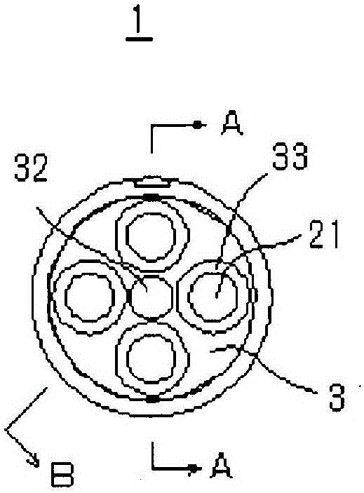
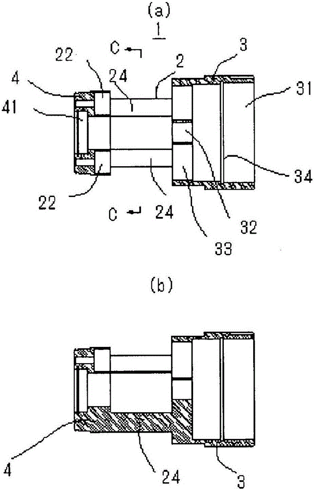
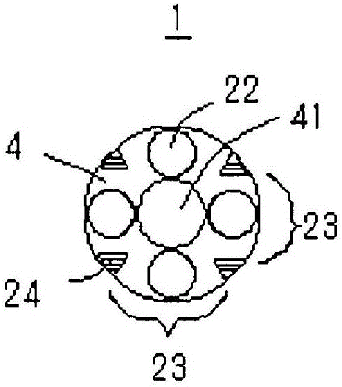
Provided is a power transmission member which allows a planetary gear mechanism to be reduced in volume while sufficient strength is guaranteed. A planetary gear holding part (2), a rotating shaft part (3), and a sun gear holding part (4) constituting a power transmission member (1) are formed integrally. The rotating shaft part (3) is substantially cylindrical, and a planetary gear (5) can be passed through the interior of the rotating shaft part (3) and turnably mounted on the planetary gear holding part (2). An open window (23) is formed in the planetary gear holding part (2), and a toothed part (53) of the planetary gear (5) is configured to mesh with a bearing-equipped outer gear (6) through the open window (23).

Description

technical field [0001] The present invention relates to a planetary gear mechanism and a member of the planetary gear mechanism that functions to transmit rotation and torque from a drive shaft to a driven shaft in the planetary gear mechanism. Background technique [0002] Conventionally, a planetary gear mechanism is known as a speed change mechanism for rotational power. As a conventionally known planetary gear mechanism, for example, there is a mechanism constituted by: a drive shaft (input shaft) to which the driving force of a drive source is transmitted to make it rotate; and a sun gear fitted to the drive shaft. And it rotates integrally with the drive shaft; the internal gear is arranged on the same axis with the sun gear with a certain gap with respect to the sun gear; a plurality of planetary gears are arranged in the above-mentioned gap at a certain angular interval and connected to the sun gear. The gear and the internal gear are meshed; the planetary carrier (...

Claims


Application Information

Patent Timeline
Patent Type & Authority Applications(China)
IPC IPC(8): F16H1/28
CPCF16H1/28F16H57/082
Inventor 当英和当导人
Owner 当英和
Learn More