Lifting device

A technology of lifting device and lifting bracket, applied in the direction of lifting device, lifting frame, etc., can solve the problems of laborious lifting and heavy weight, etc., and achieve the effect of reducing work intensity and improving work efficiency

Inactive Publication Date: 2016-10-26
NANJING ZHUOJI IND EQUIP CO LTD
View PDF10 Cites 3 Cited by
  • Summary
  • Abstract
  • Description
  • Claims
  • Application Information

AI Technical Summary

Problems solved by technology

Because the height of the parts flow basket is relatively short, if it is placed on the ground, it will inevitably cause the workers to bend over to pick up or store it. Therefore, it is necessary to manually lift it to the operating table or stack multiple parts flow baskets. Due to the After the basket is full of parts, the weight becomes very heavy, and it becomes very difficult to lift

Method used


Image

  • Lifting device
  • Lifting device
  • Lifting device

Examples


Embodiment

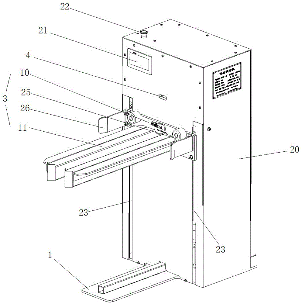
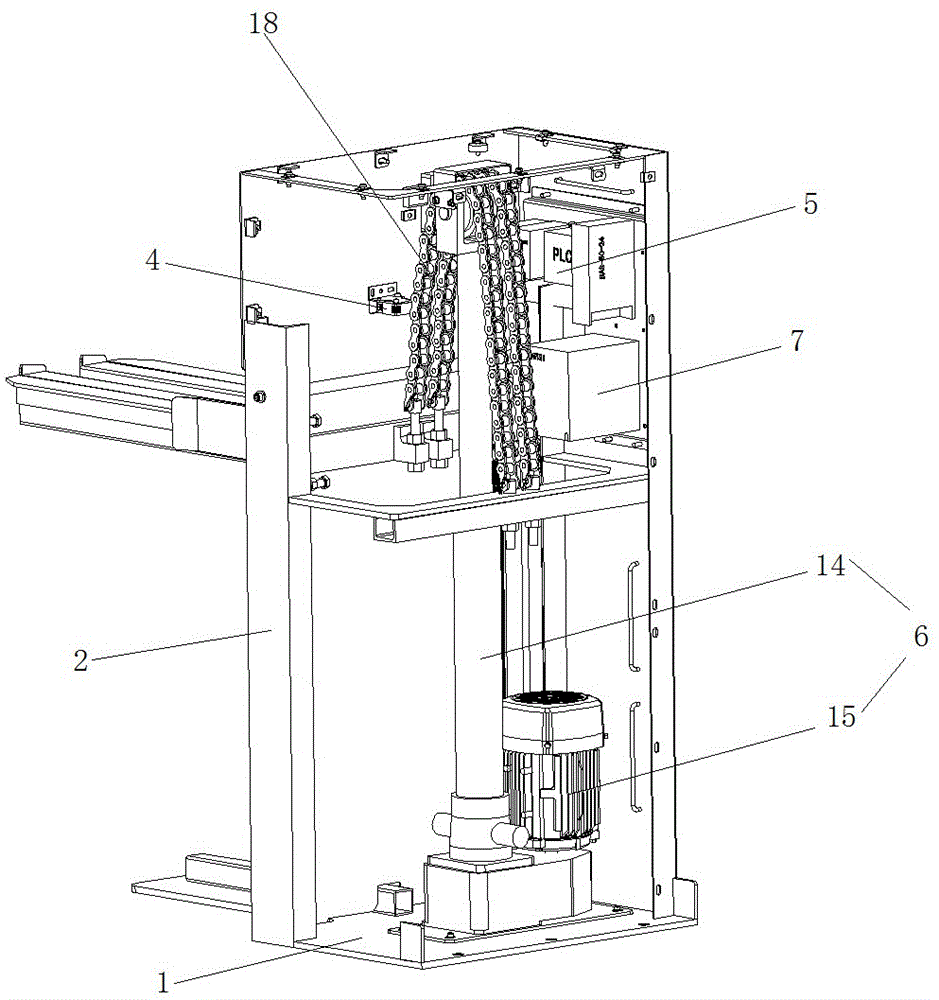
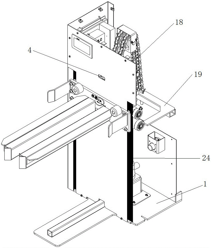
[0035] according to figure 1 , figure 2 , image 3 and Figure 4 As shown, the lifting device in the present invention includes: base 1, a pair of channel steel runways 2, telescopic cylinder assembly 6, lifting bracket assembly 3, optical sensor 4, main control single-chip microcomputer 5 and for optical sensor 4 , the main control microcontroller 5 and the power supply assembly 7 powered by the telescopic cylinder assembly 2.

[0036] Among them, such as Figure 8 and Figure 9 As shown, a pair of channel-steel runways 2 are respectively arranged on both sides of the front part of the base 1 with opposite openings.

[0037] Lifting bracket assembly 3 comprises bracket body and two groups of rollers 9 that are respectively connected to bracket body rear end both sides by roller fixing plate 8, can be as preferably: as Figure 5 and Figure 6 As shown, the bracket body is composed of a bracket fixing plate 10, a pair of bracket fork arms 11 horizontally connected on th...


PUM


Abstract

The invention relates to a lifting device, comprising: a base, a pair of channel steel runways, a telescopic cylinder assembly, a lifting bracket assembly, an optical sensor, a main control single-chip microcomputer and a power supply assembly for power supply; the pair of channel steel runways They are respectively arranged on both sides of the front of the base with opposite openings; the lifting bracket assembly includes a bracket body and two sets of rollers respectively connected to both sides of the rear end of the bracket body through roller fixing plates. The rollers are respectively embedded in the notches of the pair of channel steel runways; the lifting device in the present invention drives the movable pulley at the top of the telescopic cylinder to cooperate with the traction cable to drive the bracket body to lift, thereby driving the parts circulation basket to carry out lift. Through the lifting device in the present invention, the parts circulation basket can always be located at an ideal height, avoiding manual lifting of the parts circulation basket, improving work efficiency and reducing the work intensity of workers.

Description

technical field [0001] The invention relates to the technical field of industrial machinery, in particular to a lifting device. Background technique [0002] In modern industry, especially in the field of machinery manufacturing, a large number of parts are required for assembly. Among the wide variety of parts, especially parts such as gears are often used in large quantities. The applicant recently disclosed two kinds of vertically stackable parts circulation baskets with built-in racks corresponding to various parts in Chinese patents with publication numbers CN 205060216U and CN 205060241U respectively. Through these two parts circulation baskets, a large number of parts of different models and sizes can be placed in categories. [0003] The aforementioned two parts circulation baskets need to be placed close to the workbench of the workers when they are used in the workshop, so as to facilitate the picking and placing of parts therein. Because the height of the parts...

Claims


Application Information

Patent Timeline
Patent Type & Authority Applications(China)
IPC IPC(8): B66F7/04B66F7/28
CPCB66F7/04B66F7/28B66F2700/09
Inventor 王百春
Owner NANJING ZHUOJI IND EQUIP CO LTD
Why Eureka
Try Eureka