Material returning structure of blind flange forming die

A technology of forming die and blind hole method, which is used in manufacturing tools, forging/pressing/hammer devices, forging/pressing/hammering machines, etc., which can solve the problems of large lifting force, short service life, and easy damage to the lifting cylinder. , to achieve the effect of reducing the lifting force, simple structure and convenient installation

Inactive Publication Date: 2016-10-26
盐城中德精锻股份有限公司
View PDF0 Cites 1 Cited by
  • Summary
  • Abstract
  • Description
  • Claims
  • Application Information

AI Technical Summary

Problems solved by technology

During the material return process, because the blind hole flange is a molded forging structure, the connection between the blind hole flange and the punch is relatively tight, and the punch is fixedly connected to the punch seat through screws, the punch cannot move, and the piston rod of the jacking cylinder is lifted upwards. Blind hole flanges require a large jacking force, the jacking cylinder is easily damaged, and the service life is short

Method used


Image

  • Material returning structure of blind flange forming die

Examples


Embodiment Construction

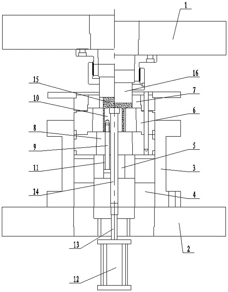
[0007] The specific content of the present invention will be described in detail below in conjunction with the accompanying drawings and specific embodiments.

[0008] Such as figure 1 As shown, the material return structure of the blind hole flange forming mold includes: an upper mold base 1 and a lower mold base 2, and a mold sleeve 3 is arranged on the upper end of the lower mold base 2, and the mold sleeve 3 is sequentially arranged from bottom to top A positioning ring 4, a punch seat 5, a lower blanking die 6 and an upper blanking die 7 are provided, and a limit seat 8 is arranged between the punch seat 5 and the lower blanking die 6. A pin 9 is slidably arranged in the limit seat 8, and the tail of the pin 9 extends into the lower blanking die 6 to be connected with the punch 10, and a sliding chamber 11 is arranged in the punch seat 5, and the pin The head of 9 is slidingly arranged in the sliding chamber 11, and a jacking cylinder 12 is arranged at the lower end of t...


PUM


Abstract

The invention discloses a blind hole flange forming mold material return structure, an upper mold base and a lower mold base, a mold sleeve is arranged on the upper end of the lower mold base, and positioning rings are sequentially arranged in the mold sleeve from bottom to top , a punch seat, a lower blank die and an upper blank die, a limit seat is set between the punch seat and the lower blank die, and a pin is slidably arranged in the limit seat, and the The tail of the pin extends into the lower blanking die and is connected with the punch. A sliding cavity is arranged in the punch seat, and the head of the pin is slidably arranged in the sliding cavity. A jacking cylinder is provided, and the piston rod of the jacking cylinder passes through the lower mold base and is connected with the ejection rod, and the ejection rod passes through the positioning ring, the punch seat, the limit seat and the punching rod in turn from bottom to top. The head is against the blind hole flange arranged in the lower blanking die and the upper blanking die.

Description

technical field [0001] The invention relates to a forming mold equipment, in particular to a material return structure of a blind hole flange forming mold. Background technique [0002] Blind hole flanges are generally formed by die pressing and forging. The mold after the blind hole flange is formed needs to be returned. The original material return structure mainly includes: an upper mold base and a lower mold base. A mold sleeve is arranged on the upper end of the lower mold base. A positioning ring, a punch seat, a lower blanking die and an upper blanking die are sequentially arranged in the die sleeve from bottom to top, and a punch is arranged in the lower blanking die, and the punch The screw is fixedly connected with the punch base, and a jacking cylinder is arranged at the lower end of the lower mold base, and the piston rod of the jacking cylinder passes through the lower mold base, the positioning ring, the punch base and the punch in turn and is arranged on the l...

Claims


Application Information

Patent Timeline
Patent Type & Authority Applications(China)
IPC IPC(8): B21J13/02B21J13/14
CPCB21J13/02B21J13/14
Inventor 沈建华殷宏彭勇
Owner 盐城中德精锻股份有限公司
Why Eureka
Try Eureka