
Long-life efficient stirring tank

A stirring tank, long-life technology, applied in the direction of dissolution, mixers, chemical instruments and methods, etc., can solve problems such as turning over, troublesome cleaning of the bottom of the mixing tank, uneven mixing of materials, etc., to achieve convenient use, improve mixing efficiency, and solutions full effect

Inactive Publication Date: 2016-10-26
WUJIANG HUAPENG CAN FACTORY
View PDF13 Cites 5 Cited by
  • Summary
  • Abstract
  • Description
  • Claims
  • Application Information

AI Technical Summary

Problems solved by technology

The mixing blades of the existing mixing tank cannot stir the material at the bottom of the mixing tank body, resulting in uneven mixing of the material, and it is also troublesome to clean the bottom of the mixing tank after the mixing is completed

Method used


Image

  • Long-life efficient stirring tank

Examples


Embodiment Construction

[0012] In order to make the technical means, creative features, goals and effects achieved by the present invention easy to understand, the present invention will be further described below in conjunction with specific embodiments.

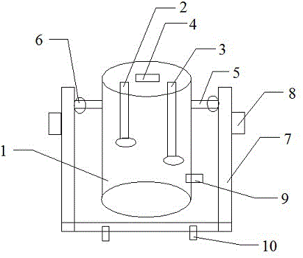
[0013] In order to achieve the above purpose, the long-life and high-efficiency stirring tank is realized by the following technical scheme: the long-life and high-efficiency stirring tank includes a main body 1, a first stirrer 2, a second stirrer 3, a feed port 4, a connecting Rod 5, connecting valve 6, support frame 7, motor 8, discharge port 9 and fixed valve 10, the first agitator 2 is vertically installed on the top left side inside the body 1, and the first agitator 2 is vertically installed on the top right side inside the body 1 Two stirrers 3, the top center inside the body 1 is vertically provided with a feed inlet 4, the outer side wall of the body 1 is equipped with a discharge port 9 at the middle and lower part, one end of the connec...


PUM


Abstract

The invention discloses a long-life efficient stirring tank, and relates to the technical field of filling containers. The long-life efficient stirring tank comprises a body (1), a first stirring device (2), a second stirring device (3), a feeding inlet (4), a connecting rod (5), a connecting valve (6), a supporting frame (7), a motor (8), a discharging outlet (9) and a fixing valve (10). According to the long-life efficient stirring tank, the stirring efficiency can be improved due to the arrangement of the stirring devices of different specifications, the time cost and the economic cost are saved, the body is driven to oscillate under the rotating action of the connecting valve, and the stirring tank can achieve internal stirring and external oscillation at the same time, so that the stirring efficiency is greatly improved. The great popularization value is achieved in the technical field of filling containers.

Description

technical field [0001] The invention relates to the technical field of filling containers, in particular to a long-life and high-efficiency stirring tank. Background technique [0002] At present, in the production fields such as medicine and chemical industry, stirring tanks are usually used to stir materials to dissolve or mix them evenly. The vertically arranged stirring shaft and the stirring blades fixed on the stirring shaft, when the stirring tank is in operation, the stirring shaft is driven by the motor arranged on the outside of the stirring tank to rotate, and the stirring shaft drives the stirring blades to rotate, so that the inside of the stirring tank material turnover. The stirring blades of the existing stirring tank cannot stir the materials at the bottom of the stirring tank body, resulting in uneven mixing of the materials, and it is troublesome to clean the bottom of the stirring tank after the stirring is completed. Contents of the invention [0003...

Claims


Application Information

Patent Timeline
Patent Type & Authority Applications(China)
IPC IPC(8): B01F11/00
CPCB01F31/26B01F31/449
Inventor 李新明
Owner WUJIANG HUAPENG CAN FACTORY
Learn More