
Optical module and optical line terminal

An optical module and terminal technology, applied in the field of optical communication, can solve the problems of limited time for the OLT processor of the optical line terminal to output high-level signals, and insufficient time for the optical module processor to maintain the connection with the charge storage, etc., to meet the time requirement desired effect

Active Publication Date: 2016-10-19
HISENSE BROADBAND MULTIMEDIA TECH
View PDF2 Cites 0 Cited by
  • Summary
  • Abstract
  • Description
  • Claims
  • Application Information

AI Technical Summary

Problems solved by technology

[0016] With the continuous improvement of sampling accuracy requirements, the length of time for the optical module processor to maintain a connection with the charge storage is also increased, and the time for the optical line terminal OLT processor to output a high-level signal is limited. The existing optical module processor and The charge storage is not kept connected long enough

Method used


Image

  • Optical module and optical line terminal
  • Optical module and optical line terminal
  • Optical module and optical line terminal

Examples


Embodiment Construction

[0036] In order to make the purpose, technical solutions and advantages of the embodiments of the present invention clearer, the technical solutions in the embodiments of the present invention will be clearly and completely described below in conjunction with the drawings in the embodiments of the present invention. Obviously, the described embodiments It is a part of embodiments of the present invention, but not all embodiments. Based on the embodiments of the present invention, all other embodiments obtained by persons of ordinary skill in the art without creative efforts fall within the protection scope of the present invention.

[0037] In an optical communication network, an optical line terminal OLT at the central office establishes connections with multiple optical network units ONUs at the user end, and multiple optical network units ONUs communicate with the same optical line terminal OLT in a time-division manner.

[0038] Specifically, the optical line terminal OLT ...


PUM


Abstract

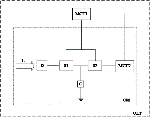
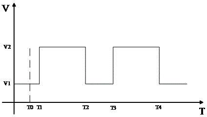
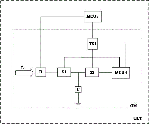
The invention provides an optical module and an optical line terminal and belongs to the optical communication field. A photosensitive component is connected to one terminal of a first switch. The other terminal of the first switch is connected to a charge storage. A control terminal of the first switch is connected to a signal output terminal of a trigger. The first switch is conducted under control of a first signal of the trigger. One terminal of a second switch is connected to the charge storage. The other terminal of the second switch is connected to an input terminal of a processor. A control terminal of the second switch is connected to the signal output terminal of the trigger. The second switch is turned off under the control of the first signal of the trigger. A signal output terminal of the processor is connected to a signal input terminal of the trigger. After carrying out voltage sampling on the charge storage, the processor outputs a second signal to the trigger. The trigger outputs the first signal to the first switch and the second switch under the control of the second signal respectively so that the processor and the charge storage maintain connection for enough time and a time need of high precision voltage sampling is satisfied.

Description

technical field [0001] The invention relates to the field of optical communication, in particular to an optical module and an optical line terminal. Background technique [0002] At present, optical communication, which uses light as a signal-carrying medium, is a communication method mainly used in the communication field. In an optical communication network, an optical line terminal OLT at the central office establishes connections with multiple optical network units ONUs at the user end, and multiple optical network units ONUs communicate with the same optical line terminal OLT in a time-division manner. [0003] Specifically, the optical line terminal OLT has an optical module, and the optical line terminal OLT controls the optical module to implement communication with the optical network unit ONU. During the communication process between the optical module and a single ONU, the optical module receives an optical signal from the ONU, and the optical signal undergoes an...

Claims


Application Information

Patent Timeline
Patent Type & Authority Applications(China)
IPC IPC(8): H04B10/40
Inventor 王魁苗壮
Owner HISENSE BROADBAND MULTIMEDIA TECH
Learn More