


Quick Research
Generate reliable direction feasibility study reports for your R&D in just a few steps.

Technical Q&A
Discover and master advanced knowledge NOW. Basics, ideas, possibilities, all at once.

Find Solutions
As an expert in R&D theories, this can generate solutions to your technical problems instantly.

Evaluate Feasibility
Analyze your overall solution with one click, know your potential R&D risks in advance.

Monitor Landscape
Get weekly tech updates, stay abreast of the latest tech innovations and key insights.
A lower electrode, dry etching equipment
An electrode and voltage technology used in the display field
- Summary
- Abstract
- Description
- Claims
- Application Information
AI Technical Summary
Problems solved by technology
Method used
Image

Examples
Embodiment 1
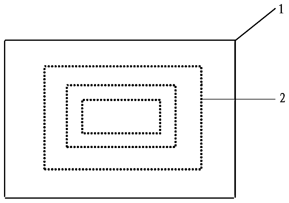
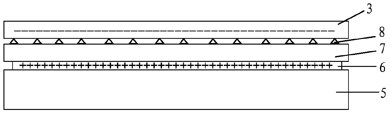
[0039] An embodiment of the present invention provides a lower electrode, referring to Figure 5 As shown, the lower electrode includes: a conductive layer 9, and a plurality of air holes 2 running through the lower electrode; a plurality of protrusions 8 are provided on the upper surface of the lower electrode; the conductive layer 9 includes: a first conductive unit 10 and a The second conductive unit 11 on the periphery of the unit 10, the first conductive unit 10 and the second conductive unit 11 are not in contact with each other; Contour limited.
[0040]The above-mentioned second conductive units may be continuously distributed on the periphery of the first conductive unit, or may be distributed at intervals on the periphery of the first conductive unit, which is not specifically limited here. The distribution of the above-mentioned pores is not limited, and in practice it is mostly according to figure 1 The word distribution shown.
[0041] In the above-mentioned lo...
Embodiment 2
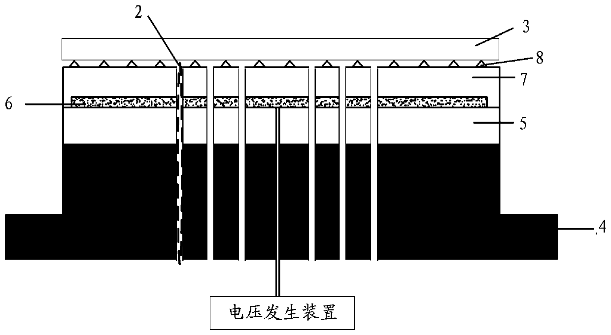
[0053] The embodiment of the present invention provides a kind of dry etching equipment, refer to Figure 9 As shown, the dry etching equipment includes: a voltage generating device 15 and a gas generating device (not shown in the figure), and the dry etching equipment also includes: any one of the lower electrodes 1 provided in Embodiment 1; The generating device 15 is used to provide voltage to the first conductive unit 10 and the second conductive unit 11 of the lower electrode 1, and the voltage provided to the first conductive unit 10 is greater than the voltage provided to the second conductive unit 11; the gas generating device is used for Cooling gas is fed upwards from the bottom of the lower electrode through the pores of the lower electrode.
[0054] The above-mentioned dry etching equipment may also include other structures such as the upper electrode, and only the structures related to the points of the present invention will be described in detail here. The gas ...
PUM
 Abstract
Description
Claims
Application Information
 - R&D Engineer
- R&D Manager
- IP Professional
- Industry Leading Data Capabilities
- Powerful AI technology
- Patent DNA Extraction
Browse by: Latest US Patents, China's latest patents, Technical Efficacy Thesaurus, Application Domain, Technology Topic, Popular Technical Reports.
© 2024 PatSnap. All rights reserved.Legal|Privacy policy|Modern Slavery Act Transparency Statement|Sitemap|About US| Contact US: help@patsnap.com