
Liquid crystal display and driving method thereof

A technology of liquid crystal display and driving method, which is applied in the field of liquid crystal display and its driving, and can solve problems such as color difference, deformation, frequent switching of liquid crystal display data signals, etc., and achieve the effect of improving color difference and improving quality

Active Publication Date: 2016-10-12
TCL CHINA STAR OPTOELECTRONICS TECH CO LTD
View PDF5 Cites 17 Cited by
  • Summary
  • Abstract
  • Description
  • Claims
  • Application Information

AI Technical Summary

Problems solved by technology

[0003] The present invention provides a liquid crystal display and its driving method to solve the technical problems in the prior art that the data signals of the liquid crystal display are frequently switched between high grayscale and low grayscale, and deformation is likely to occur, resulting in chromatic aberration.

Method used


Image

  • Liquid crystal display and driving method thereof
  • Liquid crystal display and driving method thereof
  • Liquid crystal display and driving method thereof

Examples


no. 1 approach

[0033] see Figure 4 , Figure 4 It is the first embodiment of the driving method of the liquid crystal display provided by the present invention, comprising the following steps:

[0034] S101: Obtain the first data signal of the first sub-pixel corresponding to the current scanning line and the second data of the second sub-pixel corresponding to the previous scanning line of the current scanning line and driven by the same data line as the first sub-pixel Signal.

[0035] S102: Determine a compensation value according to the first data signal and the second data signal.

[0036] S103: Compensate the first data signal by using the compensation value.

[0037] S104: Drive the first sub-pixel according to the compensated first data signal.

[0038] The driving method of the liquid crystal display provided by the present invention is provided with a compensation value, and the data signal of each sub-pixel is compensated by using the compensation value, thereby improving the...

no. 2 approach

[0039] see Figure 5 , Figure 5 It is the second embodiment of the driving method of the liquid crystal display provided by the present invention, comprising the following steps:

[0040] S201: Obtain the first data signal of the first sub-pixel corresponding to the current scanning line and the second data of the second sub-pixel corresponding to the previous scanning line of the current scanning line and driven by the same data line as the first sub-pixel Signal.

[0041] In this embodiment, each pixel of the liquid crystal display includes at least three primary color sub-pixels arranged along the column direction, wherein the at least three primary color sub-pixels are driven by the same data line and respectively correspond to different scan lines.

[0042] In practical applications, assuming that the first data signal of the first sub-pixel corresponding to the current scanning line is N, the second sub-pixel corresponding to the previous scanning line of the current ...

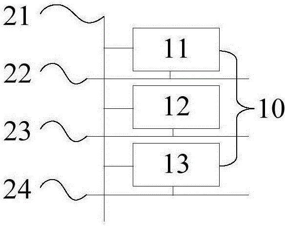

PUM


Abstract

The invention provides a liquid crystal display and a driving method thereof. The driving method comprises a step of obtaining the first data signal of a first sub pixel corresponding to a current scanning line and a second data signal of the second sub pixel which is corresponding to the previous scanning line of the current scanning line, wherein the first sub pixel and the second pixel are driven by a same data line, a step of determining a compensation value according to the first data signal and a second data signal, a step of compensating the first data signal by using the compensation value, and a step of driving the first sub pixel according to the compensated first data signal. According to the liquid crystal display and the driving method provided by the invention, due to the setting of the compensation value, the compensation value is used to compensate the data signal of each sub pixel, thus the phenomenon of a color difference of the liquid crystal display caused by data signal deformation is improved, and the quality of the liquid crystal display is improved.

Description

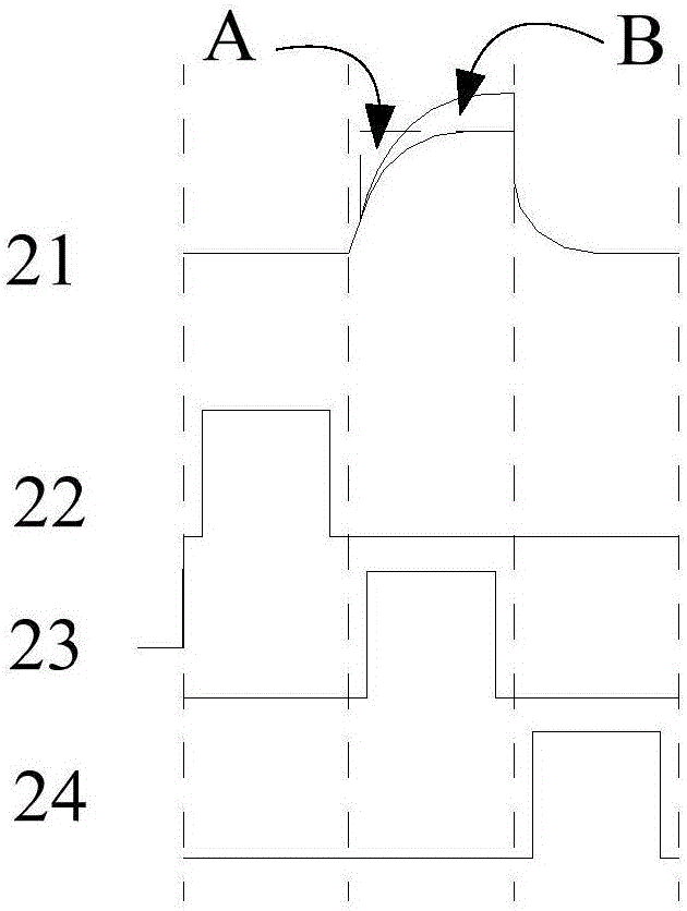
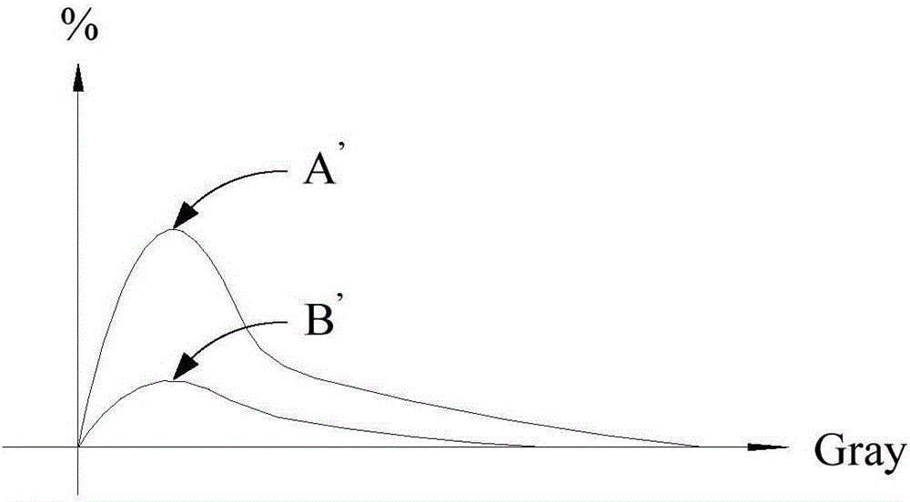
technical field [0001] The invention relates to the field of display technology, in particular to a liquid crystal display and a driving method thereof. Background technique [0002] In the field of flat panel display technology, the Tri-gate pixel driving method is a pixel with a data line (data line) and three scan lines (scan line), where a pixel includes three sub-pixels of red, green and blue . The structure of the three-gate pixel does not have the problem of data signal deformation in grayscale display, but in color display, the high grayscale and low grayscale switching of the data signal is frequent, and the data signal is easily deformed and causes brightness loss, resulting in chromatic aberration Phenomenon. Contents of the invention [0003] The present invention provides a liquid crystal display and a driving method thereof to solve the technical problem in the prior art that the data signal of the liquid crystal display is frequently switched between high ...

Claims


Application Information

Patent Timeline
Patent Type & Authority Applications(China)
IPC IPC(8): G09G3/36
CPCG09G3/3607
Inventor 崔博钦
Owner TCL CHINA STAR OPTOELECTRONICS TECH CO LTD
Learn More