
Optical module and head-mounted type display device

An optical module and module technology, applied in optics, optical components, instruments, etc., can solve problems such as affecting the visual experience, different image clarity, inability to adjust the left lens barrel assembly and the right lens barrel assembly separately, etc. Clear and guaranteed display effect

Active Publication Date: 2016-10-12
SHENZHEN KUKU TECH CO LTD
View PDF4 Cites 8 Cited by
  • Summary
  • Abstract
  • Description
  • Claims
  • Application Information

AI Technical Summary

Problems solved by technology

The existing viewing distance adjustment assembly can only adjust the viewing distance of the left lens barrel assembly and the right lens barrel assembly synchronously. The viewing distance will lead to different clarity of the image seen by the left eye and right eye when the user watches the image through the optical module, which will affect the visual experience
During the pupillary distance adjustment process of the existing pupillary distance adjustment mechanism, the left lens barrel assembly and the right lens barrel assembly relatively move with respect to the effective display screen of the display screen, resulting in the optical centers of the left lens barrel assembly and the right lens barrel assembly being aligned with each other. The display center of the display screen changes, which affects the display effect of the images displayed by the left lens barrel assembly and the right lens barrel assembly
Moreover, the existing interpupillary distance adjustment mechanism can only synchronously adjust the distance between the left lens barrel assembly and the right lens barrel assembly, and cannot individually adjust the positions of the left lens barrel assembly and the right lens barrel assembly according to the state of the wearer's interpupillary distance.

Method used


Image

  • Optical module and head-mounted type display device
  • Optical module and head-mounted type display device
  • Optical module and head-mounted type display device

Examples


Embodiment 1

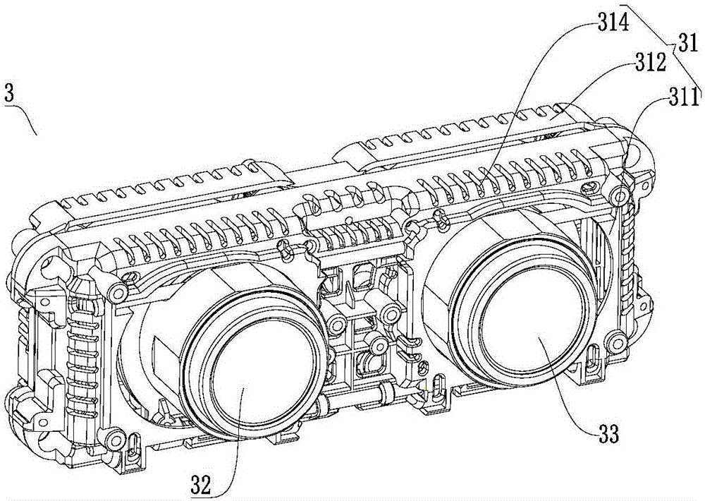
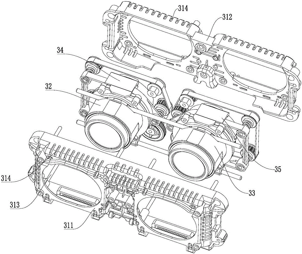
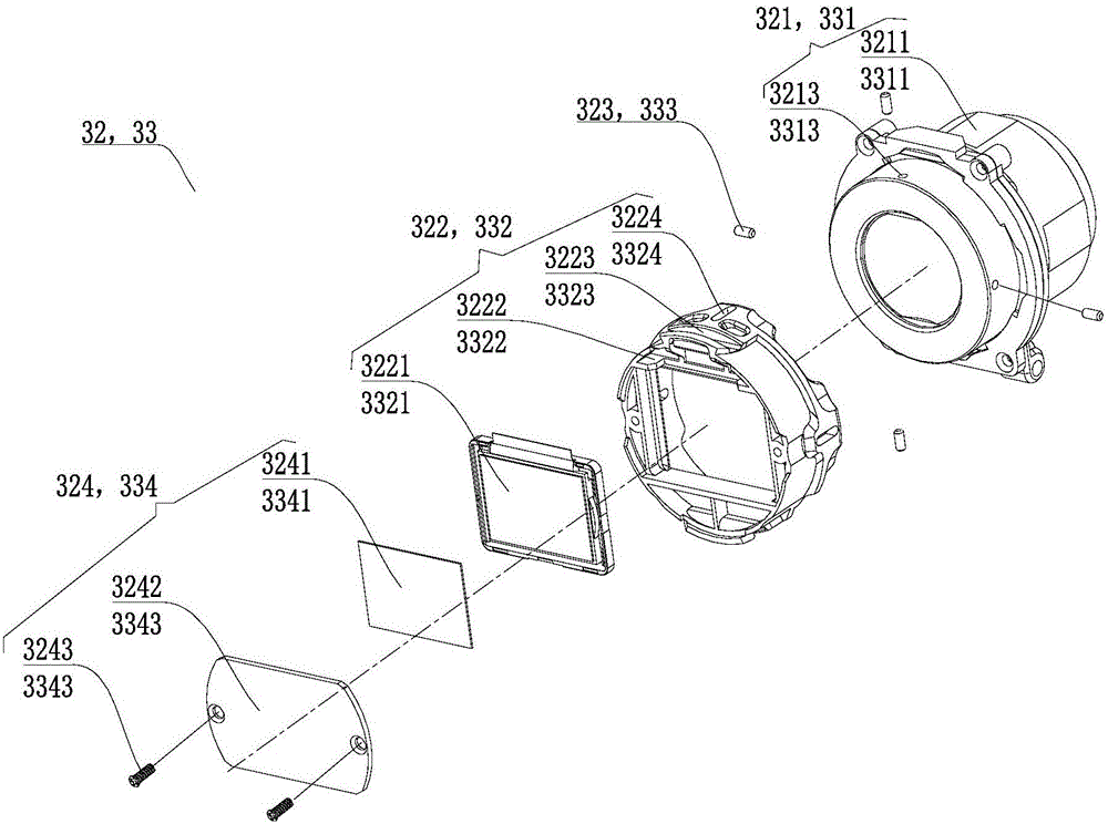
[0033] Figure 1-Figure 8 The optical module 3 in this embodiment is shown. Such as Figure 1-Figure 8 As shown, the optical module 3 includes a module housing 31, a left lens barrel mechanism 32, a right lens barrel mechanism 33, a left viewing distance adjusting mechanism 34, a right viewing distance adjusting mechanism 35, a left pupil Distance adjustment mechanism 36 and right interpupillary distance adjustment mechanism 37.

[0034] The left lens barrel mechanism 32 includes a left lens barrel assembly 321 and a left display screen 3221 arranged behind the left lens barrel assembly 321 and connected to the left lens barrel assembly 321 . Specifically, the left lens barrel mechanism 32 further includes a left display screen assembly 322 sleeved behind the left lens barrel assembly 321 , and the left display screen assembly 322 includes a left display screen 3221 and a left screen bracket 3222 for installing the left display screen 3221 . The right lens barrel mechanism ...

Embodiment 2

[0072] This embodiment provides a head-mounted display device, which includes the optical module 3 in Embodiment 1 and a headband module connected to the optical module 3 . Since left lens barrel assembly 321 and right lens barrel assembly 331 rears are respectively provided with left display screen 3221 and right display screen 3321 in optical module 3, and are provided with left viewing distance adjustment mechanism 34 adjustments and right viewing distance adjustment mechanism 35 adjustments respectively The viewing distance of the left lens barrel assembly 321 and the right lens barrel assembly 331, so that the user can adjust the viewing distance of the left lens barrel assembly 321 and the right lens barrel assembly 331 respectively according to the diopter of the left eye and the right eye, so that both eyes can see To a clearer image, to meet the needs of more users. And, since the left display screen 3221 and the right display screen 3321 are respectively provided wit...


PUM


Abstract

The invention discloses an optical module and a head-mounted type display device. The optical module comprises a module shell, and a left lens cone mechanism, a right lens cone mechanism, a left pupil distance adjusting mechanism and a right pupil distance adjusting mechanism which are arranged in the module shell. The left lens cone mechanism comprises a left lens cone assembly and a left display screen arranged behind the left lens cone assembly and connected with the left lens cone assembly. The right lens cone mechanism comprises a right lens cone assembly and a right display screen arranged behind the right lens cone assembly and connected with the right lens cone assembly. The left pupil distance adjusting mechanism is connected with the left lens cone assembly and used for driving left lens cone mechanism to move left and right. The right pupil distance adjusting mechanism is connected with the right lens cone assembly and used for driving the right lens cone mechanism to move left and right. The optical module adjusts the left eye pupil distance and the right eye pupil distance through the left pupil distance adjusting mechanism and the right pupil distance adjusting mechanism respectively, and therefore a user can see an image more clearly with two eyes through the left lens cone assembly and the right lens cone assembly; the centers of the left lens cone assembly, the right lens cone assembly, the left display screen and the right display screen can not change.

Description

technical field [0001] The invention relates to the field of display devices, in particular to an optical module and a head-mounted display device. Background technique [0002] With the development of technology and people's increasing demand for multimedia video, commonly used multimedia playback devices need to be used with an external LED or LCD display, because the pixels and size of the image displayed on the external display are limited by the size of the display and Visual effects cannot meet people's needs, and head-mounted displays have emerged as the times require. A head-mounted display (HMD for short) is an optical product for stereoscopic vision display. It is a signal with a three-dimensional effect of binocular parallax, which is sequentially transmitted through the display elements and optical lenses arranged in front of the eyes. It is sent to both eyes to produce a three-dimensional and large-size image. The head-mounted display device is usually applied...

Claims


Application Information

Patent Timeline
IPC IPC(8): G02B27/01
CPCG02B27/0176
Inventor 高胜刘军陈豪
Owner SHENZHEN KUKU TECH CO LTD
Learn More