
Series-parallel excitation device for vibrating table

An excitation device and parallel technology, applied in the field of testing, can solve problems such as large resistance value, water leakage at the faucet end, potential difference, etc., and achieve the effect of reducing voltage value, ensuring reliability, and slowing down the speed of electrochemical corrosion

Inactive Publication Date: 2016-10-12
SUZHOU DONGLING VIBRATION TEST INSTR
View PDF4 Cites 2 Cited by
  • Summary
  • Abstract
  • Description
  • Claims
  • Application Information

AI Technical Summary

Problems solved by technology

[0003] At present, the excitation coil of the water-cooled electric vibrating table generally adopts the structure of parallel connection of water circuits and series connection of circuits. The double-disk laminated winding is composed of upper and lower layers of single-disc windings in series, and all the laminated windings are stacked vertically. The double-disc laminated winding consists of a hollow tube wire from the middle to the two It is formed by straight and reverse coiling, each double-disc laminated winding tube cavity is connected in parallel to form a parallel cooling water circuit, and each double-disc laminated winding tube body is welded in series to form a series structure of the circuit. The excitation structure of this circuit series, although The structure is simple, but because each laminated winding is connected in series, the total resistance value is relatively large. In order to ensure the ampere-turn number of the excitation coil, the voltage at the input terminal of the coil is high under the condition of constant current, so the entire excitation winding There is a large potential difference between the head and the tail, which is easy to cause electrochemical corrosion of the metal faucet, which will cause water leakage at the faucet end for a long time, reducing the reliability and life of the vibrating table

Method used


Image

  • Series-parallel excitation device for vibrating table
  • Series-parallel excitation device for vibrating table

Examples


Embodiment Construction

[0016] The specific implementation manners of the present invention will be further described in detail below in conjunction with the accompanying drawings and embodiments. The following examples are used to illustrate the present invention, but are not intended to limit the scope of the present invention.

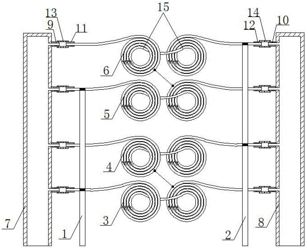
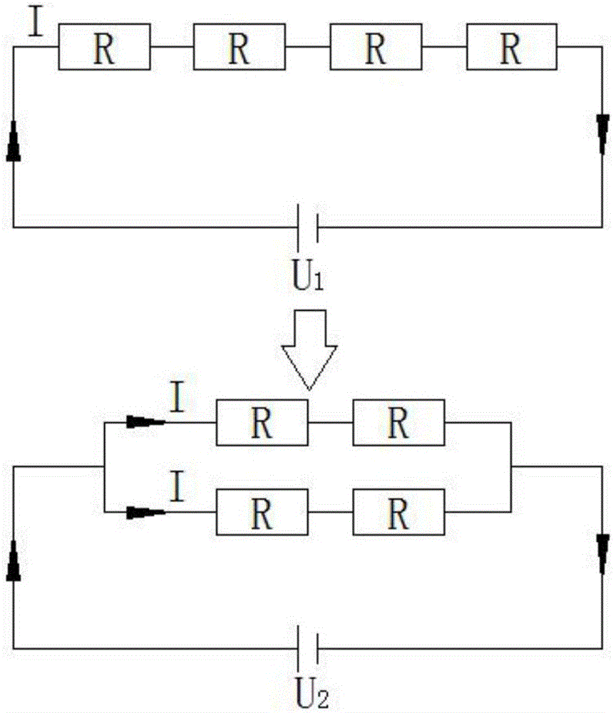
[0017] see figure 1 and figure 2 , as shown in the legend, a series-parallel excitation device for a vibrating table, including a power supply, an excitation coil, and a cooling mechanism;

[0018] The above-mentioned power supply includes a conductive positive electrode 1 and a conductive negative electrode 2;

[0019] The above excitation coil includes the first winding 3, the second winding 4, the third winding 5 and the fourth winding 6 arranged in sequence along the longitudinal direction, the end of the first winding 3 and the head end of the second winding 4 are welded together to form the upper excitation coil. The series connection; the end of the third windin...


PUM


Abstract

The invention discloses a series-parallel excitation device for a vibrating table. The series-parallel excitation device comprises a power supply and an excitation coil. The power supply has a power supply positive electrode and a power supply negative electrode. The excitation coil is formed by a plurality of windings that are arranged successively along a longitudinal direction; the windings are classified into at least two winding assemblies that are connected in parallel between the power supply positive electrode and the power supply negative electrode of the power supply; and each winding assembly consists of a winding or at least two windings connected in series. The series power supply between the laminated windings of the excitation coil is changed into a series-parallel power supply way; and thus the excitation coil is divided into an upper layer and a lower layer, the laminated windings at the upper layer and the lower layer are connected in series and then are connected in parallel. On the basis of the first-series second-parallel connecting way, the voltage value of the input terminal of the excitation winding is reduced, the electrochemical corrosion speed is reduced effectively, and reliability of the vibrating table is guaranteed.

Description

technical field [0001] The invention relates to the field of testing, in particular to a series-parallel excitation device for a vibrating table. Background technique [0002] When the excitation coil of the vibrating table is fed with direct current, a constant strong magnetic field will be generated in the magnetic circuit, and the driving coil fed with alternating current will cut the magnetic force lines in this magnetic field, and an alternating excitation force will be generated. According to different cooling methods, the vibrating table can be divided into air-cooled and water-cooled. The air-cooled vibrating table adopts fan forced air cooling, while the water-cooled coil uses hollow wires, which are powered externally and cooled by water internally. [0003] At present, the excitation coil of the water-cooled electric vibrating table generally adopts the structure of parallel connection of water circuits and series connection of circuits. The double-disk laminate...

Claims


Application Information

Patent Timeline
IPC IPC(8): G01M7/02
CPCG01M7/02
Inventor 赵征
Owner SUZHOU DONGLING VIBRATION TEST INSTR
Learn More