


Quick Research
Generate reliable direction feasibility study reports for your R&D in just a few steps.

Technical Q&A
Discover and master advanced knowledge NOW. Basics, ideas, possibilities, all at once.

Find Solutions
As an expert in R&D theories, this can generate solutions to your technical problems instantly.

Evaluate Feasibility
Analyze your overall solution with one click, know your potential R&D risks in advance.

Monitor Landscape
Get weekly tech updates, stay abreast of the latest tech innovations and key insights.
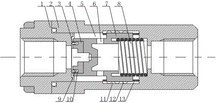
Fuel gas pipeline flow control device
A technology for flow control devices and gas pipelines, applied in valve devices, safety valves, engine components, etc., can solve problems such as gas transmission stagnation, gas reverse channeling, etc., and achieve the effects of reducing resistance, reducing weight, and avoiding mutual damage
- Summary
- Abstract
- Description
- Claims
- Application Information
AI Technical Summary
Problems solved by technology
Method used
Image

Examples
Embodiment 1
[0020] Such as figure 1 As shown, this embodiment includes a valve body 2, a tubular movable block 7 with one end closed, and a connecting head 1 whose end extends to the inside of the valve body 2. The connecting head 1 communicates with the inside of the valve body 2, and the closed end of the movable block 7 The outer diameter is smaller than the outer diameter of the open end, and there is a chute on the inner wall of the middle part of the valve body 2, and the open end of the movable block 7 is slidably arranged in the chute, and the annular space between the closed end of the movable block 7 and the chute forms a flow channel 5 , a contact block 4 is provided on the closed end face of the movable block 7, a packing ring 3 is provided on the extension end of the connecting head 1, and a protruding part 9 is installed on the packing ring 3, and the protruding part 9 It is an elastic rubber block with a triangular shape, and on the end surface of the contact block 4, there...
PUM
 Abstract
Description
Claims
Application Information
 - R&D Engineer
- R&D Manager
- IP Professional
- Industry Leading Data Capabilities
- Powerful AI technology
- Patent DNA Extraction
Browse by: Latest US Patents, China's latest patents, Technical Efficacy Thesaurus, Application Domain, Technology Topic, Popular Technical Reports.
© 2024 PatSnap. All rights reserved.Legal|Privacy policy|Modern Slavery Act Transparency Statement|Sitemap|About US| Contact US: help@patsnap.com