Multi-stage dry Roots vacuum pump

A Roots vacuum pump, dry technology, applied in the direction of rotary piston pump, pump, pump components, etc., can solve the problems of not adapting to the requirements of energy saving, environmental protection and low emission, limited vacuum degree, large volume, etc., to achieve compact structure and installation. Aspect, small size effect

Inactive Publication Date: 2016-10-12
JIANGYIN HUAXI ENERGY CONSERVATION TECH CO LTD
View PDF5 Cites 7 Cited by
  • Summary
  • Abstract
  • Description
  • Claims
  • Application Information

AI Technical Summary

Problems solved by technology

[0002] At present, in the field of vacuum applications, there are still a large number of various types of vacuum pumps that use high energy consumption and high pollution emissions, such as oil-sealed vacuum pumps such as rotary vane vacuum pumps and slide valve vacuum pumps that use a lot of oil consumption and exhaust emissions, and high energy consumption. There are a lot of waste liquid, Liquid ring vacuum pumps for exhaust gas discharge, these vacuum pumps are no longer suitable for the current national requirements for energy saving, environmental protection and low emissions;
[0003] At the same time, conventional Roots vacuum pumps are all single-stage Roots vacuum pumps, and the vacuum degree that a single-stage Roots vacuum pump can achieve is limited. Two single-stage Roots vacuum pumps are connected in series. This form of multi-stage Roots vacuum pump has multiple motors and multiple sets of cooling equipment. The multi-stage Roots vacuum pump made in this way has complex structure and volume. Huge defects, and the control is complex, the failure rate is relatively high

Method used


Image

  • Multi-stage dry Roots vacuum pump
  • Multi-stage dry Roots vacuum pump
  • Multi-stage dry Roots vacuum pump

Examples


Embodiment Construction

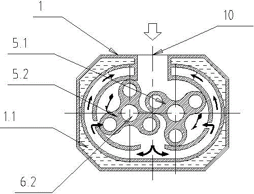
[0026] see Figure 1~4 , the present invention relates to a multi-stage dry Roots vacuum pump, the multi-stage dry Roots vacuum pump includes a pump body 1, the pump body 1 includes a cooling water spacer 1.1 wrapped in the outer layer, the The inner chamber of the pump body 1 is divided into multiple independent pump chambers along its axial direction, and each pump chamber includes an inner chamber 1.2 and an outer chamber 1.3 between the inner chamber 1.2 and the cooling water spacer 1.1 (inner chamber 1.2 and the outer cavity 1.3 are connected to each other), and the inner cavity 1.2 of the adjacent pump cavity is connected to the outer cavity 1.3 (the inner cavity 1.2 is the suction cavity, and the outer cavity 1.3 is the exhaust cavity, such as Figure 4 As shown, the exhaust chamber of the previous pump chamber is connected with the suction chamber of the latter pump chamber);

[0027] A shaft 6 is pierced through the pump body 1, and a plurality of pairs of rotors 5 a...


PUM


Abstract

The invention is a multi-stage dry Roots vacuum pump. The pump body (1) includes a cooling water spacer (1.1) wrapped in the outer layer, and the inner chamber of the pump body (1) is divided into a plurality of mutually independent Each pump cavity includes an inner cavity (1.2) and an outer cavity (1.3) between the inner cavity (1.2) and the cooling water spacer (1.1), and the inner cavity (1.2) of the adjacent pump cavity ) communicates with the outer cavity (1.3); the pump body (1) is pierced with a shaft (6), on which there are multiple pairs of rotors (5), and each pump cavity is provided with a pair of rotors (5) , the rotor (5) includes a driving rotor (5.1) and a driven rotor (5.2) that mesh with each other and are located in the inner cavity (1.2), and the driving rotor (5.1) and the driven rotor (5.2) are respectively sleeved on the driving shaft ( 6.1) and on the driven shaft (6.2). The invention discloses a multi-stage dry Roots vacuum pump, which has the advantages of simple structure, convenient use, low failure rate and the ability to meet higher vacuum degree requirements.

Description

technical field [0001] The present invention relates to a vacuum pump, in particular to a multi-stage dry Roots vacuum pump, which has no oil pollution, no waste gas, no waste liquid discharge, and can achieve a higher vacuum degree and higher multi-stage dry Roots vacuum pump. It belongs to the technical field of vacuum pumps. Background technique [0002] At present, in the field of vacuum applications, there are still a large number of various types of vacuum pumps that use high energy consumption and high pollution emissions, such as oil-sealed vacuum pumps such as rotary vane vacuum pumps and slide valve vacuum pumps that use a lot of oil consumption and exhaust emissions, and high energy consumption. There are a lot of waste liquid, Liquid ring vacuum pumps for exhaust gas discharge, these vacuum pumps are no longer suitable for the current national requirements for energy saving, environmental protection and low emissions; [0003] At the same time, conventional Root...

Claims


Application Information

Patent Timeline
IPC IPC(8): F04C23/02F04C25/02F04C29/04F04C18/12
CPCF04C23/02F04C18/126F04C25/02F04C29/04F04C2220/10
Inventor 龙晋
Owner JIANGYIN HUAXI ENERGY CONSERVATION TECH CO LTD
Why Eureka
Try Eureka