Split type universal reset stirring shaft device

A split-type, shaft-device technology, applied in the field of anti-theft locks, can solve problems such as locks not opening, failure to ensure the normal use of the clutch mechanism, and no products available.

Active Publication Date: 2016-10-12
永康市三多工贸有限公司
View PDF7 Cites 1 Cited by
  • Summary
  • Abstract
  • Description
  • Claims
  • Application Information

AI Technical Summary

Problems solved by technology

This kind of synchronous rotation between the inner and outer handles increases the operating force of the handle, and the user's operation feel is poor.
[0004] Second, when the use environment of the lock body changes, the square hole in the center of the dial shaft cannot always be in the initial vertical or horizontal state. If the lock body is just used for a lock with a clutch mechanism (such as an electronic lock), the normal operation of the clutch mechanism cannot be guaranteed. Using it will cause the lock to not open
For this reason, many manufacturers and scientific research departments have all carried out development and research, but do not have ideal product to come out so far

Method used


Image

  • Split type universal reset stirring shaft device
  • Split type universal reset stirring shaft device
  • Split type universal reset stirring shaft device

Examples


Embodiment Construction

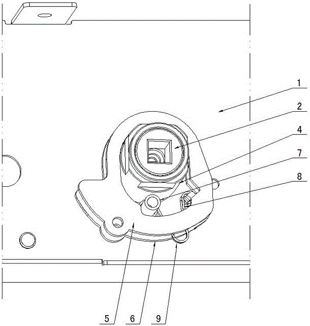
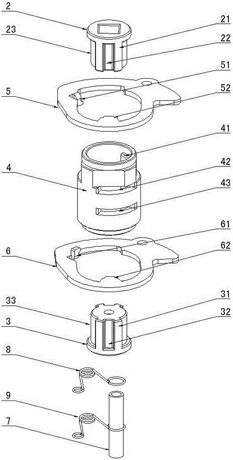
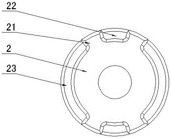
[0017] figure 1 with figure 2 As shown, the present invention creates a specific embodiment of a split-type universal reset dial shaft device, which includes first and second dial shaft cores 2, 3, dial shaft sleeves 4, first and second drive plates 5, 6 , the first dial shaft core 2 is correspondingly provided with a first limit block 21, first and second limit grooves 22, 23, and the second dial shaft core 3 is correspondingly provided with a second limit block 31, The third and fourth limiting grooves 32, 33, the first and second driving plates 5, 6 are correspondingly provided with first and second projections 52, 62, and the inner walls of the two ends of the dial shaft sleeve 4 are symmetrically provided with dial shafts Set the limit block 41, the first and second slots 42, 43 communicating with the inner hole are arranged outside the dial shaft sleeve 4, and the first and second dial shaft cores 2, 3 are symmetrically installed on both ends of the dial shaft sleeve 4...


PUM


Abstract

The invention discloses a split type universal reset stirring shaft device. The split type universal reset stirring shaft device comprises a first stirring shaft core (2), a second stirring shaft core (3), a stirring shaft sleeve (4), a first driving plate (5) and a second driving plate (6). The first stirring shaft core (2) is provided with first limiting blocks (21), first limiting grooves (22) and second limiting grooves (23), and the second stirring shaft core (3) is correspondingly provided with second limiting blocks (31), third limiting grooves (32) and fourth limiting grooves (33). The first driving plate (5) is provided with first protruding blocks (52), and the second driving plate (6) is correspondingly provided with second protruding blocks (62). The first stirring shaft core (2) and the second stirring shaft core (3) are installed at the two ends of the stirring shaft sleeve (4), stirring shaft sleeve limiting blocks (41) are correspondingly matched with the second limiting grooves (23) and the fourth limiting grooves (33), the first protruding blocks (52) of the first driving plate (5) are inserted from first inserting grooves (42) and matched with the first limiting grooves (22), and the second protruding blocks (62) of the second driving plate (6) are inserted from second inserting grooves (43) and matched with the third limiting grooves (32). After the structure is adopted, the split type universal reset stirring shaft device has the advantages of being simple and reasonable in structure, flexible and convenient to operate, capable of maintaining the stirring shaft cores in the initial perpendicular or horizontal state and the like.

Description

technical field [0001] The invention relates to the technical field of anti-theft locks, in particular to a split-type universal reset dial shaft device for an anti-theft lock dial. Background technique [0002] The dial shaft of the existing anti-theft lock is a cylindrical structural member with a square hole. The square hole in the center of the dial shaft can be a through hole, and a rectangular rod is inserted therein, and the two ends of the square rod are respectively inserted into the inner and outer handles. In the square hole; the square hole in the center of the dial shaft also has a central partition structure, which are inserted into two short square rods respectively, and the other ends of the square rods are respectively inserted into the square holes of the inner and outer handles. The disadvantages of the above structure in use: [0003] One is that regardless of the operation of the inner handle or the outer handle, the rotation of the center of the dial s...

Claims


Application Information

Patent Timeline
IPC IPC(8): E05B17/00E05B3/00
CPCE05B3/00E05B17/00
Inventor 秦攀
Owner 永康市三多工贸有限公司
Why Eureka
Try Eureka