Eureka AIR delivers breakthrough ideas for toughest innovation challenges, trusted by R&D personnel around the world.

Finish machining auxiliary positioning device for flywheel shell

An auxiliary positioning and finishing technology, applied in the field of mechanical parts processing, can solve problems such as troublesome clamping process, scratches on fixture positioning pins, large volume, etc., to save clamping time, improve work efficiency, and facilitate production.

Active Publication Date: 2016-10-12
XINXING HEAVY IND HUBEI 3611 MECHANICAL
View PDF8 Cites 3 Cited by
  • Summary
  • Abstract
  • Description
  • Claims
  • Application Information

AI Technical Summary

Problems solved by technology

[0002] At present, in the machining industry, the processing of parts generally requires several processes. The usual process is to process the reference plane and reference hole based on the preliminary positioning of the blank shape of the part, and then use the reference plane and reference hole to accurately position Process the remaining part; while the datum plane and the datum hole are usually the measurement datum of all the dimensions of a part, and they are the parts with the highest requirements for the dimension of the part, but they must be used for positioning during processing, so that during the clamping process, , the positioning surface of the workpiece and the fixture and the positioning pin will inevitably collide, which may cause certain damage to the reference surface and reference hole of the workpiece
For some small and light parts, the clamping is relatively easy, and the damage to the workpiece datum surface and datum hole is generally small, which does not affect the quality of the parts; and for some large parts, such as flywheel housings, due to their large size, The weight is heavy, and the clamping process is very troublesome. If the product is placed slightly incorrectly, it will scratch or even collide with the reference surface of the product and the positioning pin of the fixture, and the positioning pin of the fixture will scratch the reference surface of the part or even squeeze the reference hole. The situation will have an impact on the appearance quality and dimensional inspection of the parts

Method used


Image

  • Finish machining auxiliary positioning device for flywheel shell
  • Finish machining auxiliary positioning device for flywheel shell
  • Finish machining auxiliary positioning device for flywheel shell

Examples


Embodiment Construction

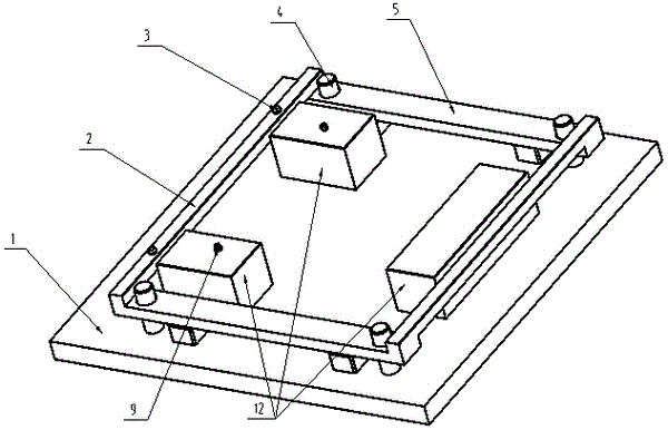
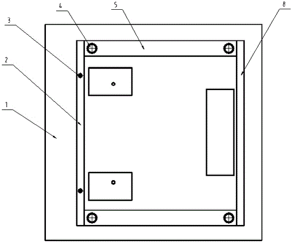
[0020] figure 1 , 2 , 3, the present invention is made up of positioning plate one 2, positioning plate two 8, protective layer 7, pre-positioning pin 3, support rod 5, guide column 4, cylinder 6. The two ends of the positioning plate one 2 and the positioning plate two 8 are connected with the two support rods 5 by welding. The protective layer is fixed on the positioning plate one 2 and the positioning plate two 8 by adhesive, and the protective layer is hard plastic. Two pre-positioning pin holes are arranged on the positioning plate-2, and the pre-positioning pin 3 is connected with the positioning plate-2 through the interference fit of the pre-positioning pin holes. A guide hole is provided on the support rod 5 , and four guide columns 4 are matched with the guide holes in a small gap, and the lower ends of the guide columns are fixed on the fixture body 1 . The cylinder 6 is fixed on the fixture body 1, and the cylinder rod is inserted into the limit hole of the supp...


PUM


Abstract

The invention provides a finish machining auxiliary positioning device for a flywheel shell. The finish machining auxiliary positioning device comprises a positioning frame, guide posts, a driving device and a bottom plate, wherein the driving device is used for driving the positioning frame to move up and down along the guide posts so that workpiece prepositioning can be conducted. The positioning frame is provided with two or more prepositioning pins. Positioning blocks are arranged in the positioning frame and provided with benchmark pins. The guide posts, the driving device and the positioning blocks are fixed to the bottom plate. Compared with the prior art, the finish machining auxiliary positioning device for the flywheel shell has the advantages of being convenient to operate, simple in structure, reliable, easy to manufacture, low in cost, easy to produce and the like; the problems that the clamping efficiency is low, and collision is prone to being caused when a flywheel shell product is subjected to finish machining are solved; the clamping time is saved; the working efficiency is improved; the product is effectively protected; and the finish machining auxiliary positioning device can be widely used in the machining process of the flywheel shell.

Description

technical field [0001] The invention belongs to a device in the processing industry of mechanical parts, in particular to an auxiliary positioning device for flywheel housing processing. Background technique [0002] At present, in the machining industry, the processing of parts generally requires several processes. The usual process is to process the reference plane and reference hole based on the preliminary positioning of the blank shape of the part, and then use the reference plane and reference hole to accurately position Process the remaining part; while the datum plane and the datum hole are usually the measurement datum of all the dimensions of a part, and they are the parts with the highest requirements for the dimension of the part, but they must be used for positioning during processing, so that during the clamping process, , The workpiece and the positioning surface of the fixture and the positioning pin will inevitably collide, which may cause certain damage to ...

Claims


Application Information

Patent Timeline
Patent Type & Authority Applications(China)
IPC IPC(8): B23Q3/08
CPCB23Q3/062B23Q3/08B23Q2703/04
Inventor 占鑫
Owner XINXING HEAVY IND HUBEI 3611 MECHANICAL
Why Eureka
Eureka Blog
Learn More