
Foldable storage stool

A technology for storing stools and stool seats, which is applied to foldable chairs, detachable chairs, other seating furniture, etc., can solve the problems of short service life, weak limit structure, damaged hinge structure, etc., and achieve long service life and reliability. The effect of good performance and simple structure

Inactive Publication Date: 2016-10-12
无锡全盛纺织品有限公司
View PDF7 Cites 2 Cited by
  • Summary
  • Abstract
  • Description
  • Claims
  • Application Information

AI Technical Summary

Problems solved by technology

[0002] In the existing foldable storage stool, the stool cap is installed behind the stool seat to form a stool. For example, the Chinese invention patent with the notification number 203709630U discloses a foldable stool, which is provided with a foldable backrest by setting a hinge device. Its hinge device adopts a hinge structure with three sections connected to each other. It adopts the longitudinal limit surface of the hinge in the middle to cooperate with the hinges at both ends to limit the rotation. However, in actual use, we found that the section in the middle The longitudinal limit surface of the hinge is only a thin layer, and its limit structure is weak and cannot withstand high pressure. In actual use, when the user leans on the backrest, the limit structure will be dislocated and damaged due to excessive force of the user. As a result, the hinge structure is damaged, affecting the normal use of the backrest, making the folding storage stool poor in reliability and short in life, and the hinge structure can only realize that the backrest is perpendicular to the seat cushion, but this vertical backrest design is less comfortable to use

Method used


Image

  • Foldable storage stool
  • Foldable storage stool
  • Foldable storage stool

Examples


Embodiment Construction

[0020] The following are specific embodiments of the present invention and in conjunction with the accompanying drawings, the technical solutions of the present invention are further described, but the present invention is not limited to these embodiments.

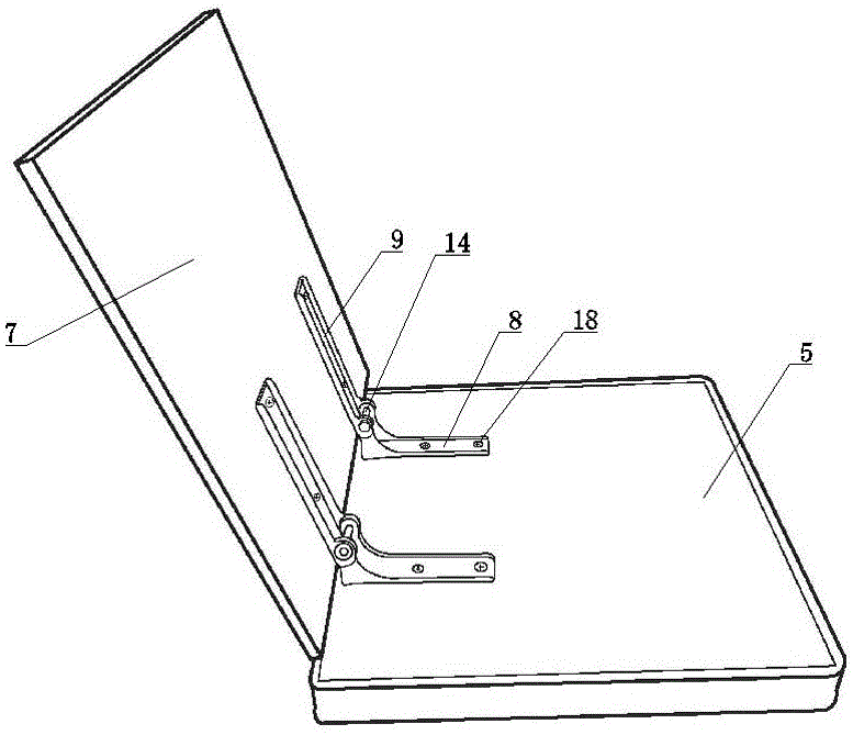
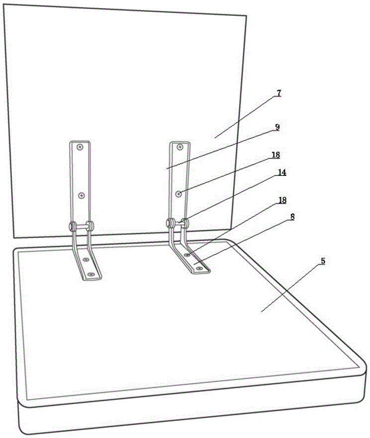
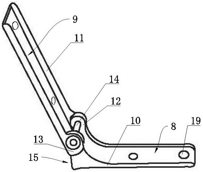
[0021] Such as figure 1 , figure 2 , image 3 , Figure 4 , Figure 5 As shown, a storage folding stool of the present invention includes a foldable stool seat 1 and a stool cap 2 set on the stool seat 1, the stool cap 2 includes a seat stool 3 and a backrest 4 connected by rotation, and the seat stool 3 includes a bottom plate 5 and the soft surface layer covered on the base plate 5, the backrest 4 includes a hard plate 7 and a soft surface layer covering the upper surface and the lower surface of the hard plate 7, the hard plate 7 and the base plate 5 are rotatably connected by a hinge device, The hinge device comprises a first hinge 8 and a second hinge 9 of a rotational link, and the first hinge 8 and the second h...


PUM


Abstract

The invention provides a foldable storage stool which is simple in structure, good in reliability and long in service life and comprises a foldable stool seat and a stool cover arranged on the stool seat in a sleeving mode. The stool cover comprises a stool body and a backrest which are connected in a rotary mode, wherein the stool body comprises a base plate, the backrest comprises a hard plate, the hard plate and the base plate are connected through a hinge device in a rotary mode, a first hinge of the hinge device is fixed to the upper surface of the base plate, a second hinge is fixed to the lower surface of the hard plate, first side walls respectively in the length direction of the first hinge are correspondingly arranged on two sides of the first hinge in the width direction, second side walls respectively in the length direction of the second hinge are correspondingly arranged on two sides of the second hinge in the width direction, a first connecting lug is arranged at one end of each of two first side walls, a second connecting lug is arranged at one end of each of two second side walls, the first connecting lugs are correspondingly located on the inner sides of the second connecting lugs, limiting faces are arranged on the outer sides of the first connecting lugs and are matched with the second hinge for rotary limiting.

Description

technical field [0001] The invention relates to the technical field of stool structures, in particular to a folding storage stool. Background technique [0002] In the existing foldable storage stool, the stool cap is installed behind the stool seat to form a stool. For example, the Chinese invention patent with the notification number 203709630U discloses a foldable stool, which is provided with a foldable backrest by setting a hinge device. Its hinge device adopts a hinge structure with three sections connected to each other. It adopts the longitudinal limit surface of the hinge in the middle to cooperate with the hinges at both ends to limit the rotation. However, in actual use, we found that the section in the middle The longitudinal limit surface of the hinge is only a thin layer, and its limit structure is weak and cannot withstand high pressure. In actual use, when the user leans on the backrest, the limit structure will be dislocated and damaged due to excessive forc...

Claims


Application Information

Patent Timeline
Patent Type & Authority Applications(China)
IPC IPC(8): A47C4/30F16C11/04
CPCA47C4/30F16C11/04
Inventor 盛建刚
Owner 无锡全盛纺织品有限公司
Learn More