
Power supply module and bridging apparatus thereof

A technology of power module and bridging device, applied in the direction of circuit device, emergency power supply arrangement, electrical components, etc., can solve the problems of space waste, complicated process, low product reliability, etc., achieve simplified process, reduce setting distance, and increase product reliability degree of effect

Active Publication Date: 2016-10-05
DELTA ELECTRONICS INC
View PDF4 Cites 0 Cited by
  • Summary
  • Abstract
  • Description
  • Claims
  • Application Information

AI Technical Summary

Problems solved by technology

[0006] The purpose of the present invention is to provide a power supply module and its bridging device, so that two circuit boards are connected through the bridging device and constructed as a conductive path, so as to solve the existing problems of relatively complicated process, low product reliability and waste of space

Method used


Image

  • Power supply module and bridging apparatus thereof
  • Power supply module and bridging apparatus thereof
  • Power supply module and bridging apparatus thereof

Examples


Embodiment Construction

[0056] Some typical embodiments embodying the features and advantages of the present invention will be described in detail in the description in the following paragraphs. It should be understood that the present invention can have various changes in different implementations without departing from the scope of the present invention, and the description and drawings in the description are used for illustration in nature rather than limiting the scope of the present invention. invention.

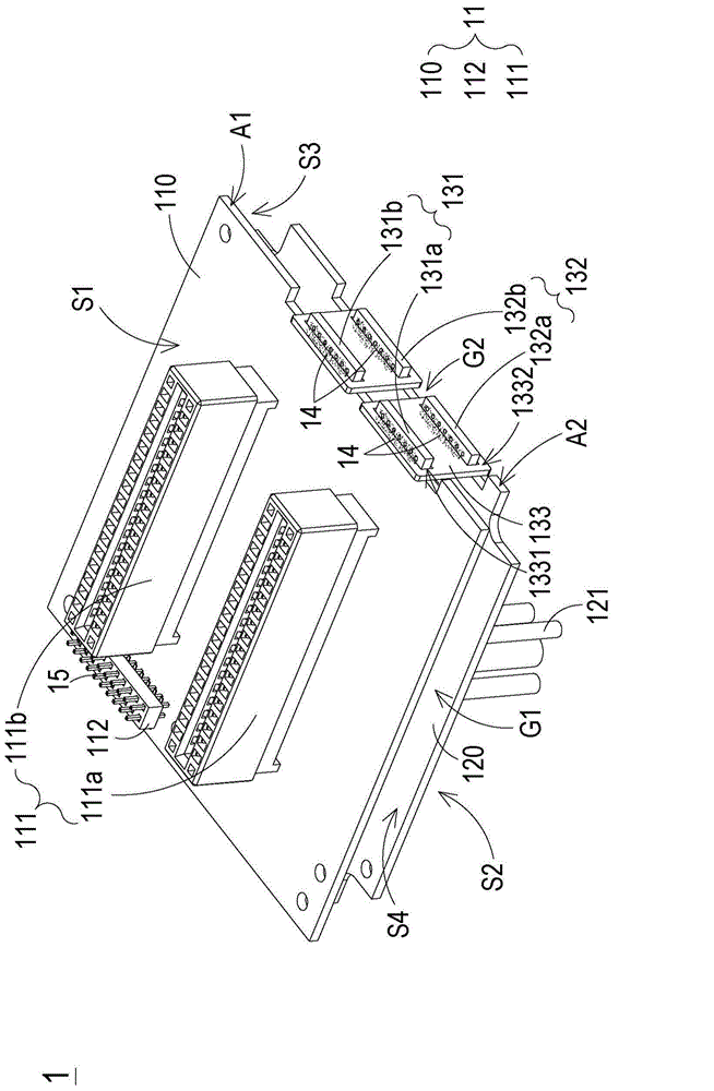
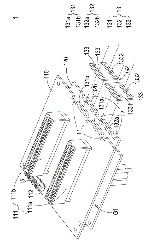
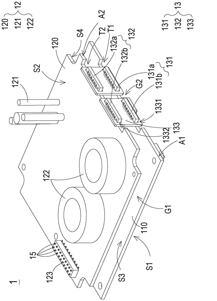
[0057] see figure 1 and cooperate figure 2and image 3 , figure 1 It is a three-dimensional structural schematic diagram of a power module in a preferred embodiment of the present invention; figure 2 for figure 1 a schematic diagram of the exploded structure of the power module shown; and image 3 for figure 1 The schematic diagram of the rear structure of the power module shown. Such as figure 1 As shown, the power module 1 includes a first circuit board 11 , a second circuit board...


PUM


Abstract

The invention discloses a power supply module. The module comprises a first circuit board, a second circuit board and a bridging apparatus. A first connection interface is arranged on a first surface of the first circuit board. A second connection interface is arranged on a second surface of the second circuit board. The bridging apparatus comprises a first conductive portion, a second conductive portion and a third conductive portion. The first conductive portion is arranged on a first setting surface of the first circuit board and is connected to the opposite first connection interface. The second conductive portion is arranged on a second setting surface of the second circuit board and is connected to the opposite second connection interface. A first setting hole of the third conductive portion sleeves the first conductive portion. A second setting hole of the third conductive portion sleeves the second conductive portion. A power supply is transmitted to the second connection interface from the first connection interface via the first conductive portion, the third conductive portion and the second conductive portion. Back sides of the two circuit boards are arranged in a face to face mode so that the connection interfaces and other components are arranged on opposite sides of the circuit boards; product reliability is increased and a space utilization rate is improved.

Description

technical field [0001] The invention relates to a power module and its bridge device, in particular to a power module and its bridge device which can simplify the process and save the installation space. Background technique [0002] With the vigorous development of various electronic devices, the demand for power supply systems is also increasing. In order to ensure the normal operation of electronic devices and avoid data loss or equipment failure caused by sudden power interruptions, more and more electronic devices use backup power. Assisted power supply system. The redundant power supply system is to integrate multiple main power supplies and a backup power supply in parallel into the same power supply system, and when any main power supply fails to operate suddenly, it can be The backup power supply provides continuous power supply to avoid sudden shutdown of electronic equipment, resulting in data loss or equipment failure. [0003] The existing redundant power supp...

Claims


Application Information

Patent Timeline
Patent Type & Authority Applications(China)
IPC IPC(8): H02J9/04
Inventor 廖士庆陈鸿川
Owner DELTA ELECTRONICS INC
Learn More