Combined beam connecting structure with welding studs and application thereof
A technology for connecting structures and composite beams, which is applied in bridges, bridge parts, bridge construction, etc., can solve problems such as the gap between the upper spliced plate and the steel beam, the large load of the steel beam, and the weak combination of steel and concrete, so as to achieve enhanced strength and Reliability, reduce production and installation costs, and speed up construction
- Summary
- Abstract
- Description
- Claims
- Application Information
AI Technical Summary
Problems solved by technology
Method used
Image
Examples
Embodiment 1
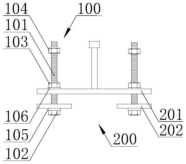
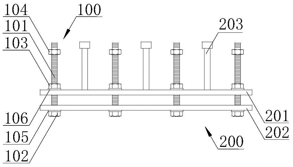
[0040] A composite beam connection structure 300 with welding studs, its combined section and elevation are as follows figure 1 and figure 2 As shown, it is mainly used for steel and concrete composite beams, which includes a spliced plate group 200 . The splice board group 200 includes a large splice board 201 and a small splice board 202 . Several welding studs 203 are welded on the large splicing plate. The splicing plate group 200 is provided with at least two sets of bolt groups 100 capable of connecting with steel beams. The bolt set 100 includes a threaded screw 101 , a fixing nut 102 , a fastening nut 103 , an anchor nut 104 , a washer 105 and a washer 2 106 . Wherein, the first gasket 105 is located between the fixing nut 102 and the small splicing plate 202 , and the second gasket 106 is located between the fastening nut 103 and the large splicing plate 201 . The fixing nut 102 is located at the lower surface of the steel beam flange, and the free end of the t...
Embodiment 2
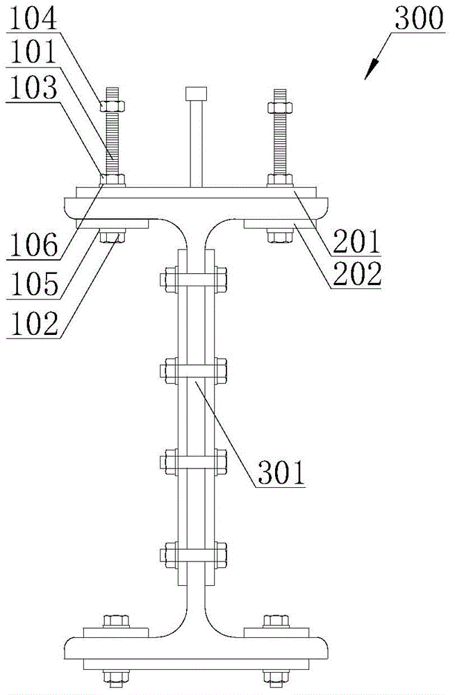
[0044] Combined Sectional View image 3 and elevations Figure 4 The composite beam connection structure 300 with welding studs of the present invention is described. The difference from Embodiment 1 is that the composite beam connection structure 300 with welding studs of this embodiment also includes at least two sections of steel beams 301, spliced plate groups 200 is connected with steel beam 301 through at least two sets of bolt groups 100 . Steel girder 301 is shaped steel girder and welded steel girder, and is steel plate girder, steel box girder and steel truss girder. The contact surface of the spliced plate group 200 and the top plate of the steel beam 301 adopts an anti-corrosion coating system that meets the requirements of the friction surface.
Embodiment 3
[0046] Combined Sectional View Figure 5 and elevations Figure 6 Illustrate that the composite beam 400 containing the composite beam connection structure with welding studs of the present invention includes a concrete slab 401 that can be cast at one time on site, cast in sections, or partially prefabricated and cast in place, and at least one set of concrete slabs located at the bottom of the concrete 401 Composite beam connection structure 300 with welding studs. The fixed end of the threaded screw 101 in the composite beam connection structure 300 with welding studs is located on the bottom surface of the upper flange of the steel beam 301, and the free end of the threaded screw 101 passes through the upper flange of the steel beam 301 and the splicing plate group 200 and is buried In the concrete post-casting section 401. The drilling accuracy of the bolt holes of the spliced plate group 200 and the steel beam 301 is the same as that required for high-strength bolt h...
PUM
 Abstract
Description
Claims
Application Information
 - Generate Ideas
- Intellectual Property
- Life Sciences
- Materials
- Tech Scout
- Unparalleled Data Quality
- Higher Quality Content
- 60% Fewer Hallucinations
Browse by: Latest US Patents, China's latest patents, Technical Efficacy Thesaurus, Application Domain, Technology Topic, Popular Technical Reports.
© 2025 PatSnap. All rights reserved.Legal|Privacy policy|Modern Slavery Act Transparency Statement|Sitemap|About US| Contact US: help@patsnap.com


