
Sliding door structure for air conditioner

A technology for sliding doors and air conditioners, applied to airflow control elements and other directions, can solve the problems of difficulty in ensuring motion stability, large resistance of moving parts, and reduced reliability of motion mechanisms, so as to increase running stability and reliability, reduce Frictional resistance, the effect of reducing frictional resistance

Active Publication Date: 2016-09-28
AUX AIR CONDITIONING LTD BY SHARE LTD
View PDF7 Cites 14 Cited by
  • Summary
  • Abstract
  • Description
  • Claims
  • Application Information

AI Technical Summary

Problems solved by technology

[0004] In the rack and pinion mechanism mentioned above, the resistance is generated by the sliding friction between the rack and the track during the movement process. Due to the large coefficient of sliding friction, the resistance of the traditional moving parts is large, which has extremely high requirements on the power output and the quality of the parts. Stability is difficult to be guaranteed; while the output power increases, the noise generated also increases; due to friction and mechanism wear, the reliability of the motion mechanism is also greatly reduced; in addition, because only the upper and lower ends of the sliding door The movement mechanism is set, and the sliding door has a certain height, which may easily cause the sliding door to be unstable when sliding and reduce the reliability

Method used


Image

  • Sliding door structure for air conditioner
  • Sliding door structure for air conditioner
  • Sliding door structure for air conditioner

Examples


Embodiment Construction

[0026] The present invention will be further described in detail below in conjunction with the accompanying drawings and embodiments.

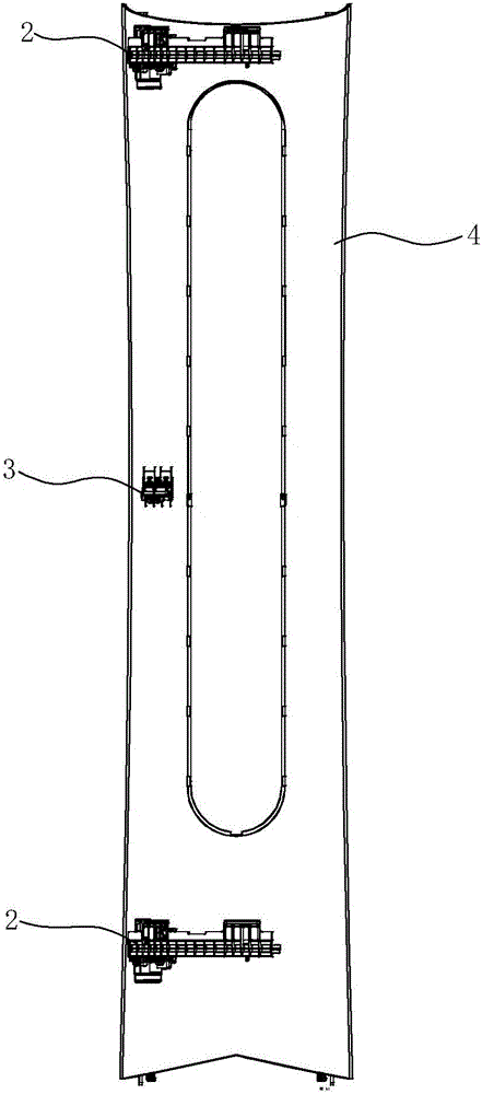
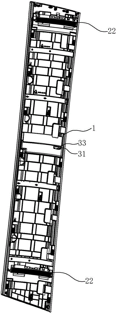
[0027] see Figure 1 ~ Figure 3 , an air conditioner sliding door structure, including a sliding door component 1 and a movement mechanism, the movement mechanism includes a driving device 2 and a slide rail device 3 . Wherein, the sliding door part 1 includes a sliding door 11. In order to simplify the manufacturing process and save materials, the sliding door part 1 also includes a sliding door lining positioned on the inner side of the sliding door 11 (when the sliding door 11 is installed, the side facing the front panel of the air conditioner) The panel 12, the sliding door 11 and the sliding door liner 12 are fixed by a cover plate 13 at the upper end. The above-mentioned moving mechanism is arranged on the inner side of the sliding door component 1, between the sliding door component 1 and the front panel.

[0028] see Figure 4 ~ Fi...


PUM


Abstract

The invention discloses a sliding door structure for an air conditioner. The sliding door structure comprises a sliding door component, a front panel and a movement mechanism arranged between the sliding door component and the front panel. The movement mechanism comprises an upper drive device and a lower drive device which are arranged in a spaced manner. Each drive device comprises a drive mechanism arranged on the outer side of the front panel and a rack, wherein each rack is arranged on the inner side of the sliding door component and is driven by the corresponding drive mechanism to transversely slide. The sliding door structure for the air conditioner is characterized in that the movement mechanism further comprises a sliding rail device used for limiting the movement locus of the sliding door component, and the sliding rail device is arranged between the two drive devices; and by additionally arranging the sliding rail device in the middle, the movement locus of the sliding door component is limited, and the supporting effect on the sliding door component can be enhanced, so that the sliding door component slides more stably and reliably.

Description

technical field [0001] The invention relates to an air conditioner, in particular to an air conditioner sliding door structure. Background technique [0002] With the development of the air-conditioning industry, people's living standards are constantly improving, and consumers have higher requirements for air-conditioning noise, comfort, appearance, etc., so there are more and more types of air-conditioners. A common air conditioner has an air outlet panel body, and an air outlet is arranged on the air outlet panel body, through which hot air or cold air is provided to the room. When the air conditioner is in a closed state, the air outlet is still exposed, and at this time, dust and other pollutants can easily enter the air conditioner, thereby affecting the normal operation of the air conditioner. At the same time, the exposure of the air outlet will also affect the appearance of the air conditioner. [0003] Therefore, more and more air conditioners use a fully enclose...

Claims


Application Information

Patent Timeline
IPC IPC(8): F24F13/12
CPCF24F13/12
Inventor 谢斌吴庆壮张玉忠张小红郑宇杰吴俊戴光军罗会斌
Owner AUX AIR CONDITIONING LTD BY SHARE LTD
Learn More