Unmanned aerial vehicle body structure, groove assisting positioning platform and landing positioning method of unmanned aerial vehicle

An auxiliary positioning and unmanned aerial vehicle technology, applied in the field of unmanned aerial vehicles, can solve the problems of complex control technology, high cost of control mechanism, difficulty in further improving landing positioning accuracy, etc., to achieve reduced control cost, improved landing positioning accuracy, and good friction Effect

Active Publication Date: 2016-09-28
傲飞创新科技(深圳)有限公司
View PDF11 Cites 14 Cited by
  • Summary
  • Abstract
  • Description
  • Claims
  • Application Information

AI Technical Summary

Problems solved by technology

[0006] The above-mentioned UAV landing and positioning technologies all adopt the current mainstream GPS positioning and are assisted by image recognition and positioning, sound-assisted positioning, ultrasonic-assisted positioning, infrared-assisted positioning, etc. The control technology is complicated, the cost of the control mechanism is high, and the landing positioning accuracy is still difficult. Further improve

Method used


Image

  • Unmanned aerial vehicle body structure, groove assisting positioning platform and landing positioning method of unmanned aerial vehicle
  • Unmanned aerial vehicle body structure, groove assisting positioning platform and landing positioning method of unmanned aerial vehicle
  • Unmanned aerial vehicle body structure, groove assisting positioning platform and landing positioning method of unmanned aerial vehicle

Examples


Embodiment 1

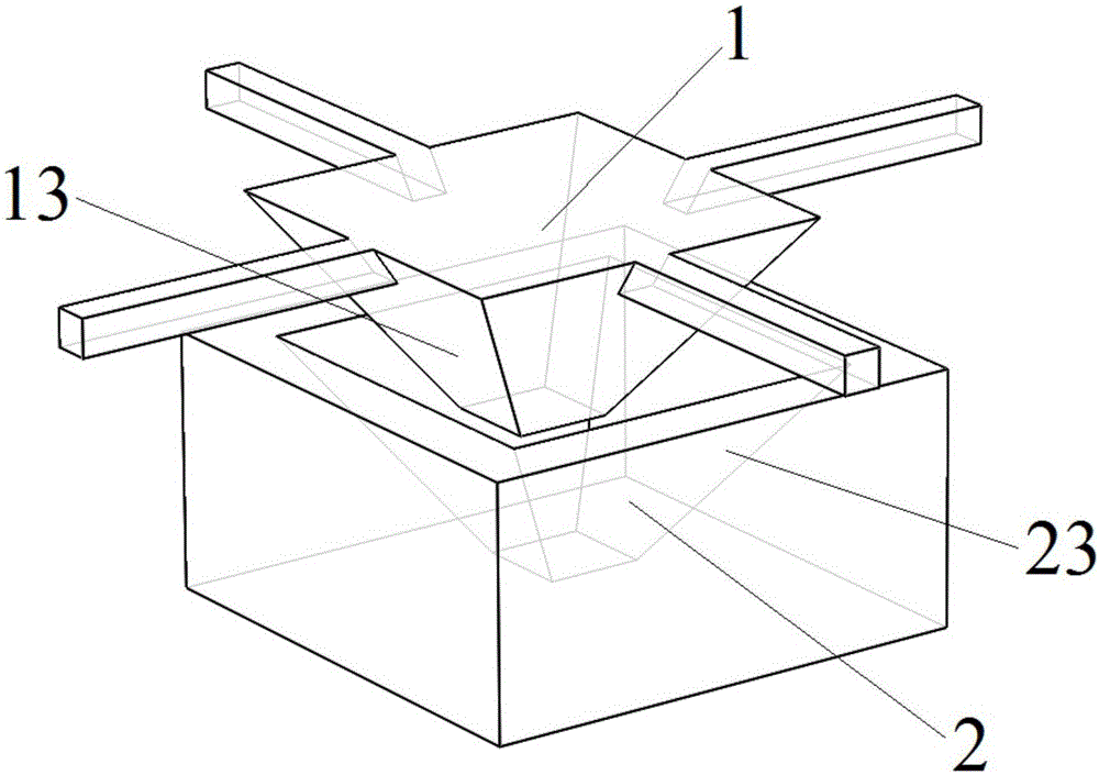
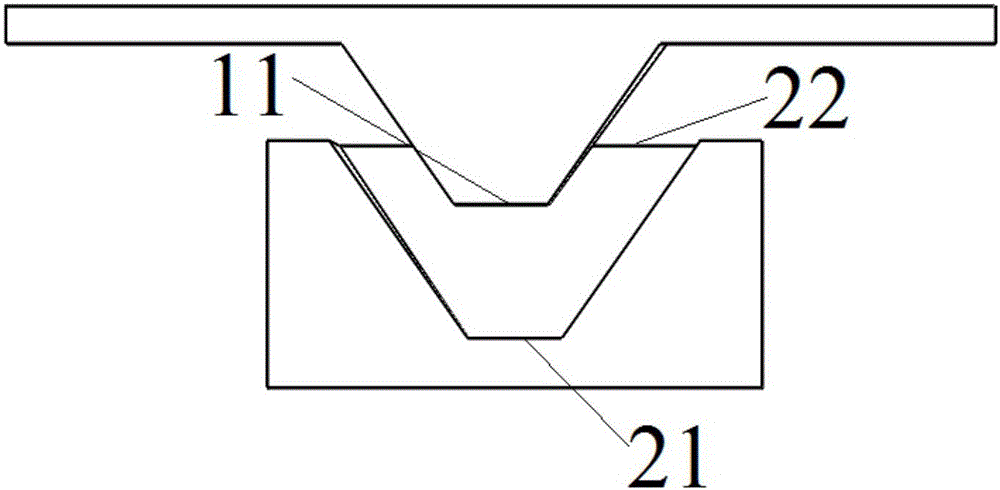
[0047] Please refer to the attached figure 1 with 2 , the fuselage structure of the UAV in the present invention adopts the following design: the fuselage 1 as a whole is a retracted structure with a large top and a small bottom, including:

[0048] The bottom surface of the fuselage 11, the bottom surface of the fuselage directly coincides with the bottom surface 21 of the groove after the UAV docks;

[0049] the fuselage top surface, located on top of the fuselage; and

[0050] A plurality of side surfaces 13 of the fuselage are located between the bottom surface 11 of the fuselage and the top surface of the fuselage, and intersect with the bottom surface 11 of the fuselage and the top surface of the fuselage to form straight or arc edges. Groove sides 23 match;

[0051] The plurality of sides 13 of the fuselage intersect to form an edge, and the edge shares a vertex with the straight edge or arc edge;

[0052] The area formed by the multiple straight or arc edges inters...

Embodiment 2

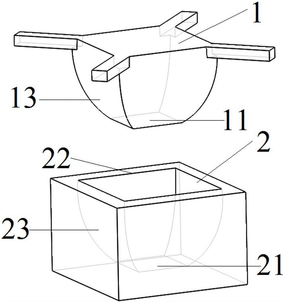
[0070] Please refer to the attached image 3 with 4 , the structure design of the UAV fuselage, the groove structure design of the groove auxiliary positioning platform and the landing positioning method of this embodiment are basically the same as those in Embodiment 1, but the curved surface design is adopted on the side of the UAV fuselage and the groove side, Correspondingly, the straight line edges in Embodiment 1 are changed to arc edges. The side of the fuselage and the side of the groove adopt a curved surface to replace the plane structure of the cone slope, which can better reduce friction and make the drone slide into the groove of the groove-assisted positioning platform more smoothly.


PUM


Abstract

The invention discloses an unmanned aerial vehicle body structure, a groove assisting positioning platform and a landing positioning method of an unmanned aerial vehicle. The unmanned aerial vehicle body structure adopts structural design of an inverted cone with edges, and is matched with the groove assisting positioning platform of which side surfaces of a groove are provided with edges. Under the guidance of the side surfaces of the groove and the restriction of the edges of the side surfaces of the groove, the unmanned aerial vehicle voluntarily adjusts angles to slide to the bottom surface of the groove along the side surfaces of the groove. Physical auxiliary positioning is mainly adopted by the landing positioning method disclosed by the invention, so that the control cost is greatly reduced, and the landing positioning accuracy is notably improved.

Description

technical field [0001] The invention relates to the technical field of unmanned aerial vehicles, and particularly discloses an unmanned aerial vehicle body structure, a groove auxiliary positioning platform and a landing positioning method thereof. Background technique [0002] Unmanned aircraft, referred to as "drone" for short, and "UAV" for English abbreviation, is an unmanned aircraft controlled by radio remote control equipment and its own program control device. The control technology of UAV take-off and landing has received extensive attention, especially the precise landing technology of UAV, and attempts have been made to introduce technologies such as GPS positioning, sonar ranging, and infrared ranging. [0003] Patent CN105182994A discloses a method for fixed-point landing of UAVs, which combines GPS and computer vision technology for high-precision fixed-point landing methods: first, calculate the hovering height of the UAV's return flight; the second step is to...

Claims


Application Information

Patent Timeline
Patent Type & Authority Applications(China)
IPC IPC(8): B64C1/00B64D45/06B64C27/08
CPCB64C1/00B64C27/08B64C2001/0045B64D45/06
Inventor 文放魏俊豪
Owner 傲飞创新科技(深圳)有限公司
Why Eureka
Try Eureka