a spray can

A sprayer and tank technology, which is applied in the field of sprayer tanks, can solve problems such as insufficient grip, and achieve the effects of labor-saving pressing, narrowing distance, and high friction

Active Publication Date: 2018-11-06
金之铖(江苏)包装科技股份有限公司
View PDF6 Cites 0 Cited by
  • Summary
  • Abstract
  • Description
  • Claims
  • Application Information

AI Technical Summary

Problems solved by technology

[0003] For hand-held sprayers, the cans are smaller, but because the cans are usually injection molded plastic with a smooth outer surface, the grip is not stable enough for use

Method used


Image

  • a spray can
  • a spray can
  • a spray can

Examples


Embodiment Construction

[0021] The following are specific embodiments of the present invention and in conjunction with the accompanying drawings, the technical solutions of the present invention are further described, but the present invention is not limited to these embodiments.

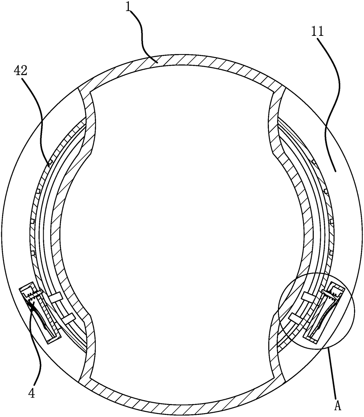
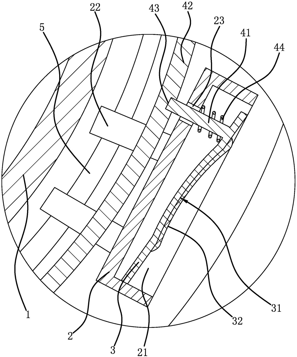
[0022] Such as figure 1 , figure 2 As shown, an aerosol tank includes a cylindrical tank body 1, the tank body 1 is made of plastic, and the outer peripheral wall of the tank body 1 has two strip-shaped concave cavities 11 in the upper direction, and the length of the two concave cavities 11 is The direction is arranged along the circumference of the tank body 1, and the two concave cavities 11 are symmetrically arranged. The seat body 2 is slidably connected along the length direction in the concave cavity 11, and a pressing groove 21 is opened on the outer surface of the seat body 2, and a pressing groove 21 is hinged in the pressing groove 21. The pressing plate 3 is provided between the pressing plate 3 and the tank ...


PUM


Abstract

The invention provides a sprayer tank, and belongs to the technical field of sprayers. The sprayer tank solves the problem that an existing sprayer tank can not be stably held when used. The sprayer tank comprises a cylindrical tank body, the peripheral wall of the tank body is provided with two long-strip-shaped cavities in the circumferential direction, bases are connected in the cavities in a sliding mode in the length direction, pressing grooves are formed in the outer side faces of the bases, pressing pates are hinged in the pressing grooves, and positioning pieces are arranged between the pressing plates and the tank and can fix the bases when the pressing plates are pressed and get close to the bottom faces of the cavities. The sprayer tank can be more conveniently and more stably held, and the use comfort can be increased.

Description

technical field [0001] The invention belongs to the technical field of sprayers and relates to a sprayer tank. Background technique [0002] Sprayer is the abbreviation of spray equipment. A sprayer is a device that uses air suction to turn a liquid medicine or other liquid into a mist and sprays it evenly on other objects. Automatic sprayer, electric sprayer, etc., any sprayer includes a tank for holding the solution, but the size and shape of the tank are different. [0003] As for the handheld sprayer, the tank body is small, but because the tank body is usually made of plastic injection molding and has a smooth outer surface, it is not stable enough to hold when using it. Contents of the invention [0004] The object of the present invention is to solve the above-mentioned problems in the existing technology, and propose an aerosol can, which is more convenient and stable to hold, and improves the comfort of use. [0005] The purpose of the present invention can be ...

Claims


Application Information

Patent Timeline
Patent Type & Authority Patents(China)
IPC IPC(8): A01M7/00
CPCA01M7/0085B05B7/2402
Inventor 吴韩祺
Owner 金之铖(江苏)包装科技股份有限公司
Why Eureka
Try Eureka