LED lamp bracket and lamp comprising same
A technology of LED lamp bracket and lamp beads, applied in the field of lighting, can solve the problem that LED cannot be used directly, and achieve the effect of smooth transition
- Summary
- Abstract
- Description
- Claims
- Application Information
AI Technical Summary
Problems solved by technology
Method used
Image
Examples
Embodiment 1
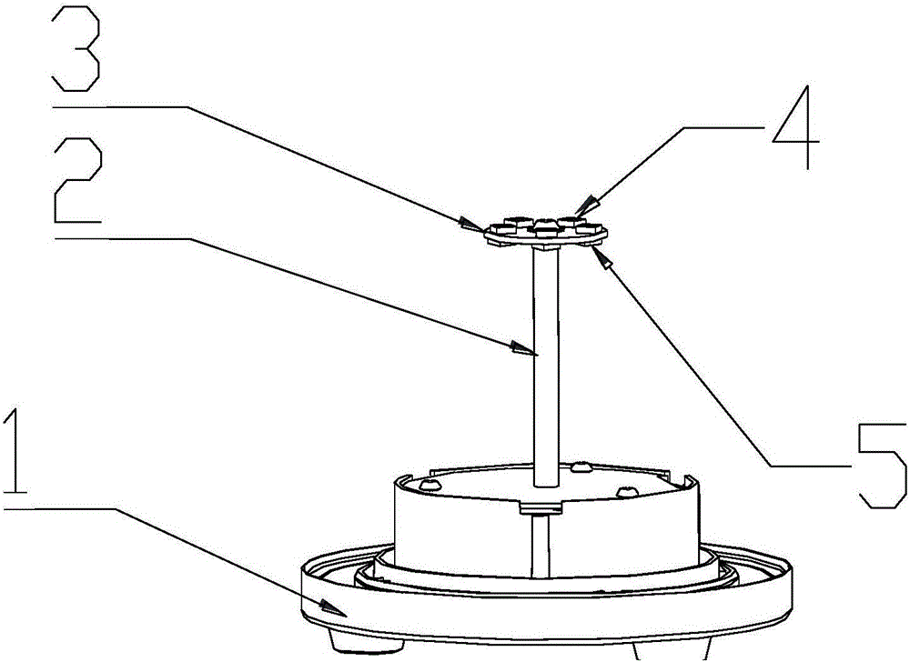
[0029] see first figure 1 As shown, it is a structural schematic diagram of Embodiment 1 of the present invention. The bracket of the present invention includes a base 1, a pole 2 and a disk 3, and the disk 3 is connected to the base 1 through the pole 2. connect.
[0030] The disk 3 has two upper and lower surfaces, which are respectively called the upper surface of the disk and the lower surface of the disk. The upper surface of the disk is provided with the first luminescent layer 4, and the lower surface of the disk is provided with the second luminescent layer. 5. The first light-emitting layer 4 and the second light-emitting layer 5 respectively include several light-emitting structures, and the light-emitting structures may be lamp beads, lamp bead chips, and other similar point light sources, which are not limited in the present invention.
[0031] Due to the effect of the isolation structure of the disc 3, the first luminescent layer 4 and the second luminescent laye...
Embodiment 2
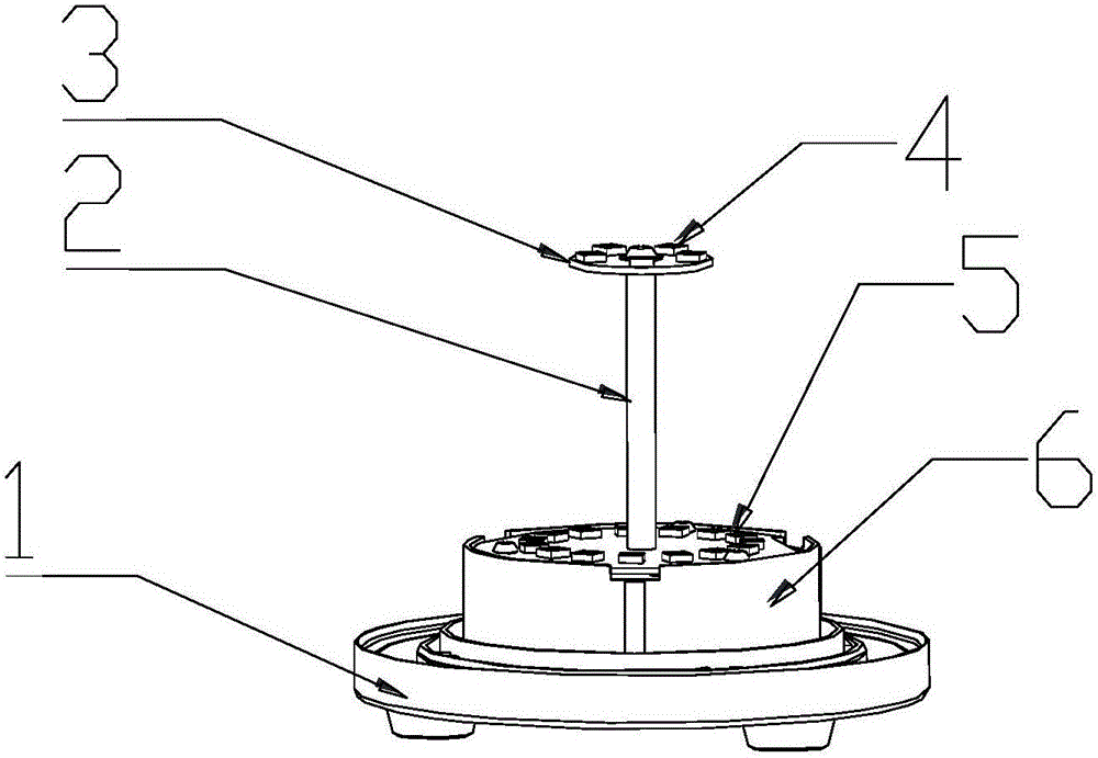
[0034] See figure 2 As shown, it is a schematic structural diagram of Embodiment 1 of the present invention.
[0035] figure 2 The shown structure has some adjustments based on the first embodiment, specifically, the base 1 includes a base disc 6, and the second luminescent layer 5 is arranged on the base disc.
[0036] In this way, also due to the isolation effect of the disc 3, the light emitted by the first luminous layer 4 and the second luminous layer 5 have different irradiation ranges, realizing the illumination of the same lamp and different areas with different colors. Moreover, as the structure described in the second embodiment, since the first light-emitting layer 4 and the second light-emitting layer 5 both emit light upward, they are particularly suitable for environments with upward lighting, such as floor lamps and bedside lamps.
Embodiment 3
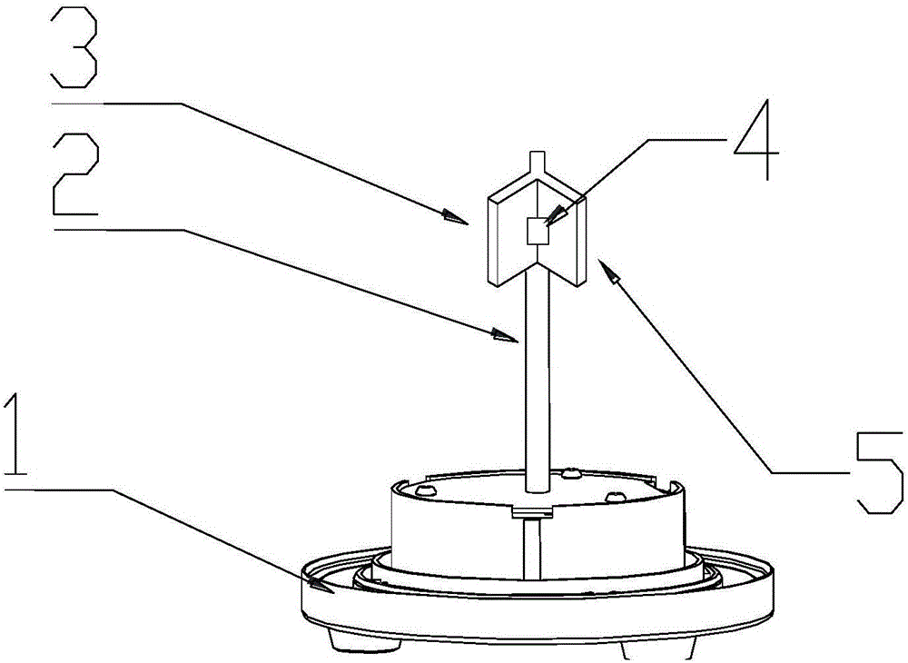
[0038] See image 3 As shown, it is a schematic structural diagram of Embodiment 3 of the present invention.
[0039] Embodiment 3 has made some adjustments on the basis of Embodiment 1, mainly because the disk 3 in Embodiment 1 is replaced by a column isolation structure 3 in Embodiment 3, and the isolation structure 3 is a Y-shaped cross-sectional structure , the axis is the same as or parallel to the axis of the pole 2, and the isolation structure 3 has three concave parts, such as image 3 As shown, the first light-emitting layer 4 is disposed in one of the recessed parts, and the second light-emitting layer 5 is disposed in the other recessed part, so that the first light-emitting layer 4 and the second light-emitting layer 5 The direction of the lighting is isolated and shines in different directions.
[0040] It is worth pointing out that the above introduces a variety of structural embodiments of the isolation structure. In fact, as long as the isolation of the light...
PUM
 Abstract
Description
Claims
Application Information
 - R&D
- Intellectual Property
- Life Sciences
- Materials
- Tech Scout
- Unparalleled Data Quality
- Higher Quality Content
- 60% Fewer Hallucinations
Browse by: Latest US Patents, China's latest patents, Technical Efficacy Thesaurus, Application Domain, Technology Topic, Popular Technical Reports.
© 2025 PatSnap. All rights reserved.Legal|Privacy policy|Modern Slavery Act Transparency Statement|Sitemap|About US| Contact US: help@patsnap.com


