
Intelligent end effector device for assembling screw

An end-effector and screw-driving technology, which is used in metal processing equipment, metal processing, manufacturing tools, etc., can solve the problems of difficult product quality assurance, low screw-driving efficiency, and high assembly success rate, and achieves good support stability and locking. The effect of high compaction efficiency and high success rate

Active Publication Date: 2016-09-14
HUAZHONG UNIV OF SCI & TECH +1
View PDF6 Cites 9 Cited by
  • Summary
  • Abstract
  • Description
  • Claims
  • Application Information

AI Technical Summary

Problems solved by technology

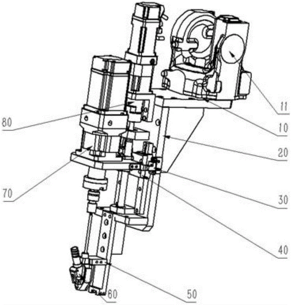
[0004] In view of the above defects or improvement needs of the prior art, the present invention provides an intelligent screw-driving end effector device, in which an end-effector suitable for screw-driving is designed in combination with the technological characteristics of screw-driving, and its key components Such as joint joint plate, joint flange, guide rail slider mechanism, photoelectric sensor, servo motor system, and the structure and specific setting of the screw storage bin are studied and designed, which can effectively solve the low efficiency of manual screw driving. , poor consistency, and difficult to guarantee product quality. It has the advantages of high assembly efficiency, low labor intensity, and high assembly success rate.

Method used


Image

  • Intelligent end effector device for assembling screw
  • Intelligent end effector device for assembling screw
  • Intelligent end effector device for assembling screw

Examples


Embodiment Construction

[0033] In order to make the object, technical solution and advantages of the present invention clearer, the present invention will be further described in detail below in conjunction with the accompanying drawings and embodiments. It should be understood that the specific embodiments described here are only used to explain the present invention, not to limit the present invention. In addition, the technical features involved in the various embodiments of the present invention described below can be combined with each other as long as they do not constitute a conflict with each other.

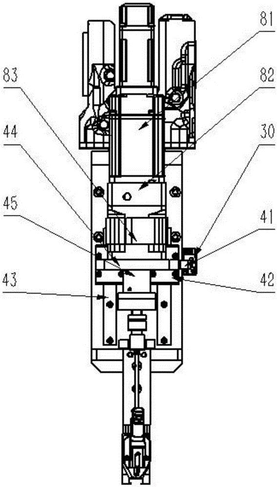
[0034] Such as figure 1 As shown, a screw driving end effector device provided by an embodiment of the present invention mainly includes a robot joint connecting plate 20, a connecting flange 10, a guide rail slider mechanism 40, a photoelectric sensor 30, a servo motor system A80, a servo The motor system B70 and the screw storage bin 60, wherein the robot joint joint plate 20 is used as a bas...


PUM


Abstract

The invention discloses an intelligent end effector device for assembling a screw. The device comprises a robot joint connecting plate, a guide rail slide block mechanism, a photoelectric sensor, a servo motor system A, a servo motor system B and a screw storing bin, wherein the robot joint connecting plate is L-shaped and comprises a tail end and a head end; two lead screw mounting plates are correspondingly horizontally arranged at the top and bottom of the head end, and the photoelectric sensor is mounted on the side surface of the head end; the guide rail slide block mechanism is mounted on the head end and is positioned between the two lead screw mounting plates; a servo motor mounting plate is horizontally arranged on the guide rail slide block mechanism; the servo motor system A is arranged at the upper part of the head end; the servo motor system B for controlling a screwdriver to rotate is arranged on the servo motor mounting plate; the screw storing bin for storing the screw is mounted at the lower part of the head end and is arranged below the servo motor system B. the device is used in match with a robot and has the advantages of being high in assembling efficiency, high in success rate and low in labor intensity.

Description

technical field [0001] The invention belongs to the field of automatic screwing devices, and more specifically relates to an intelligent screwing end effector device, which is suitable for large-scale intelligent assembly lines. Background technique [0002] On the assembly line of various products, screwing is the most basic operation, which consumes a lot of manpower and material resources. In the traditional assembly process, manual screwdrivers are mostly used for tightening. With the emergence of electric / pneumatic screwdrivers, the efficiency of screwing has improved. A certain improvement has been achieved, but a large amount of manual work is still required. Manual assembly is time-consuming and laborious, and the production efficiency is low. It is difficult to guarantee assembly process and product consistency, which often leads to short product life or various problems during operation. [0003] In order to solve the above problems, many automatic screw machines h...

Claims


Application Information

Patent Timeline
Patent Type & Authority Applications(China)
IPC IPC(8): B23P19/00B23P19/06
CPCB23P19/001B23P19/06
Inventor 许剑锋吴忠鼎刘趁伟师威孙权权卓弘阳臧艺凯
Owner HUAZHONG UNIV OF SCI & TECH
Learn More