Arrangement method of integrated intercooler of air inlet manifold
A technology of intake manifold and layout method, which is applied in the direction of intake muffler, machine/engine, combustion air/combustion-air treatment, etc., which can solve the problem of degassing and cleaning, difficulty in filling cooling system, and risk of cavitation To achieve the effect of convenient layout, reducing the risk of cavitation and ensuring the reliability of work
Inactive Publication Date: 2016-09-07
CHERY AUTOMOBILE CO LTD
View PDF6 Cites 0 Cited by
- Summary
- Abstract
- Description
- Claims
- Application Information
AI Technical Summary
Problems solved by technology
like figure 1 As shown, when arranging the intake manifold integrated intercooler 1, due to the consideration of the assembly space of the intake manifold bolt 2, the intercooler is placed too high, exceeding the MIN line of the expansion tank, making it difficult to fill the cooling system And degassing is not clean, there is a risk of cavitation
Method used
View moreImage
Smart ImageViewing Examples
Examples
Embodiment Construction
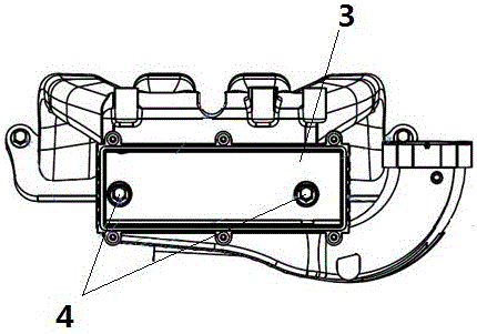
[0012] Such as figure 2 As shown, the resonant cavity 3 of the intake manifold is provided with bolts 4, and the intake manifold and the engine cylinder head are fixed by the bolts 4. When arranging, the intake manifold and the engine cylinder head are first fixed, and then the intercooler is installed in the resonant cavity 3 of the intake manifold. When the intake manifold is fixed to the engine cylinder head, fasten the bolts 4 in the resonant cavity 3 of the intake manifold.
Login to view more PUM
![No PUM](https://static-eureka-patsnap-com.libproxy1.nus.edu.sg/ssr/23.2.0/_nuxt/noPUMSmall.5c5f49c7.png)
Abstract
The invention relates to an arrangement method of an integrated intercooler of an air inlet manifold. A resonant cavity of the air inlet manifold and an engine cylinder cover are fixed through bolts. According to the arrangement method, the resonant cavity of the air inlet manifold and the engine cylinder cover are fixed through the bolts creatively, the assembling space of an existing air inlet manifold bolt does not need to be considered any more during arrangement of the intercooler, the intercooler can be properly and reasonably arranged according to the flow direction of airflow and the position of an expansion box, the cavitation risk of a cooling system is effectively reduced, and the overall work reliability of an engine is guaranteed.
Description
technical field [0001] The invention relates to an arrangement method of an intake manifold integrated intercooler. Background technique [0002] In the prior art, more and more supercharged engines adopt the intake manifold integrated intercooler technology, which greatly shortens the pipeline length from the compressor outlet to the inlet inlet, reduces the volume of the intake system, and the engine The transient response characteristics are significantly improved. Such as figure 1 As shown, when arranging the intake manifold integrated intercooler 1, due to the consideration of the assembly space of the intake manifold bolt 2, the intercooler is placed too high, exceeding the MIN line of the expansion tank, making it difficult to fill the cooling system And degassing is not clean, there is a risk of cavitation. Contents of the invention [0003] The object of the present invention is to provide a method for arranging an intake manifold integrated intercooler, which ...
Claims
Login to view more Application Information
Patent Timeline
![application no application](https://static-eureka-patsnap-com.libproxy1.nus.edu.sg/ssr/23.2.0/_nuxt/application.06fe782c.png)
Patent Type & Authority Applications(China)
IPC IPC(8): F02M35/12F02B29/04
CPCF02B29/04F02M35/1283F02M35/1288Y02T10/12
Inventor 张春雷李少清韩艳艳
Owner CHERY AUTOMOBILE CO LTD
- R&D Engineer
- R&D Manager
- IP Professional
Why Eureka
- Industry Leading Data Capabilities
- Powerful AI technology
- Patent DNA Extraction
Try Eureka
Browse by: Latest US Patents, China's latest patents, Technical Efficacy Thesaurus, Application Domain, Technology Topic.
© 2024 PatSnap. All rights reserved.Legal|Privacy policy|Modern Slavery Act Transparency Statement|Sitemap