Adjustable multifrequency antenna
A multi-frequency antenna and center frequency technology, applied to the antenna, the device that enables the antenna to work in different bands at the same time, the structural form of the radiation element, etc., can solve the problem that the antenna volume cannot be significantly saved, and achieve the effect of increasing the number
- Summary
- Abstract
- Description
- Claims
- Application Information
AI Technical Summary
Problems solved by technology
Method used
Image

Examples
Embodiment 1
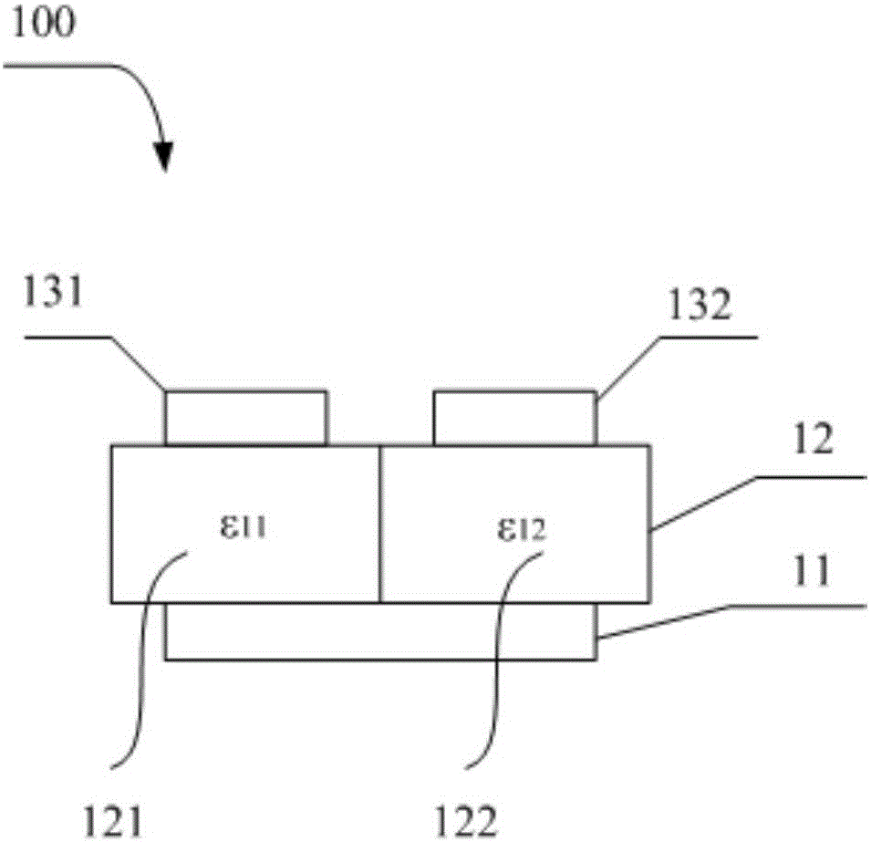
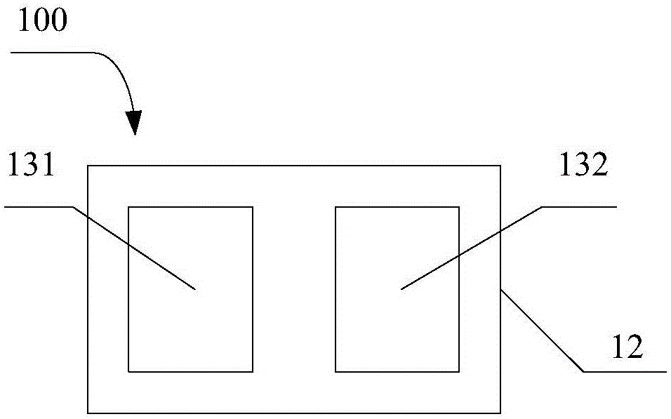
[0036] This embodiment provides an adjustable multi-frequency antenna, see Figure 1~2 , the adjustable multi-frequency antenna 100 includes: a ground plate 11 , a dielectric substrate 12 , a first radiation patch 131 and a second radiation patch 132 . The ground plate 11 is a conductive material connected to the ground, usually a copper plate or tin foil. The dielectric substrate 12 is provided on the ground plate 11 . The dielectric substrate 12 includes a first dielectric part 121 and a second dielectric part 122, and the first and second dielectric parts are respectively composed of a first dielectric constant ε 11 and the second permittivity ε 12 made of materials. The first radiation patch 131 is disposed on the dielectric substrate 12 at a position corresponding to the first dielectric part 121, thereby having a first resonant center frequency f 11 . The second radiation patch 132 is disposed on the dielectric substrate 12 at a position corresponding to the second ...
Embodiment 2
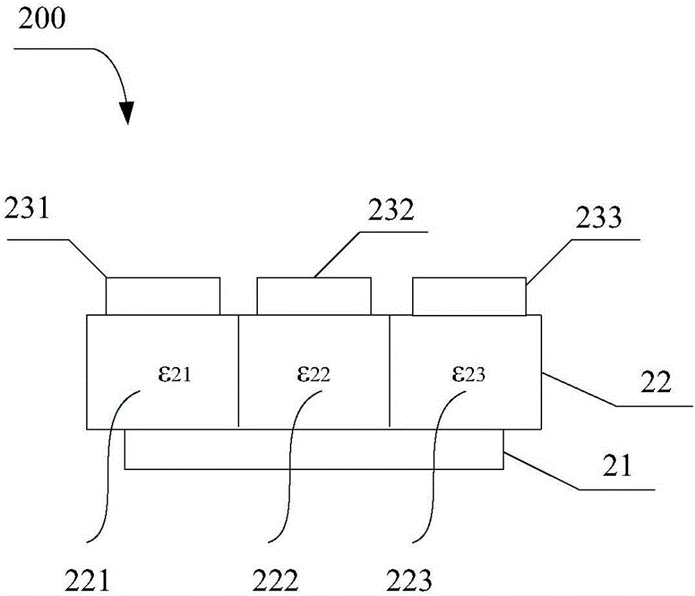
[0041] This embodiment provides another adjustable multi-frequency antenna, such as image 3 and 4 As shown, the adjustable multi-frequency antenna 200 includes: a ground plate 21 , a dielectric substrate 22 , a first radiation patch 231 , a second radiation patch 232 and a third radiation patch 233 . The ground plate 21 is a conductive material connected to the ground, and is usually a copper plate or tin foil. The dielectric substrate 22 is provided on the ground plate 21 . The dielectric substrate 22 includes a first dielectric part 221, a second dielectric part 222 and a third dielectric part 223, and the first, second and third dielectric parts are respectively composed of a first dielectric constant ε 21 , the second permittivity ε 22 and the third permittivity ε 23 made of materials. The first radiation patch 231 is disposed on the dielectric substrate 22 at a position corresponding to the first dielectric part 221, thereby having a resonant center frequency f 21 ...
Embodiment 3
[0049] This embodiment provides another adjustable multi-frequency antenna structure, such as Figure 5-6 As shown, the adjustable multi-frequency antenna 300 includes: a ground plate 31 , a dielectric substrate 32 , a first radiation patch 331 , a second radiation patch 332 , a third radiation patch 333 and a fourth radiation patch 334 . The ground plate 31 is a conductive material connected to the ground, and is usually a copper plate or tin foil. The dielectric substrate 32 is provided on the ground plate 31 . The dielectric substrate 32 includes a first dielectric part 321, a second dielectric part 322, a third dielectric part 323 and a fourth dielectric part 324, and the first, second, third and fourth dielectric parts are respectively composed of a first dielectric constant ε 31 , the second permittivity ε 32 , the third permittivity ε 33 and the fourth permittivity ε 34 made of materials. The first radiation patch 331 is disposed on the dielectric substrate 32 at a...
PUM
 Abstract
Description
Claims
Application Information
 - R&D
- Intellectual Property
- Life Sciences
- Materials
- Tech Scout
- Unparalleled Data Quality
- Higher Quality Content
- 60% Fewer Hallucinations
Browse by: Latest US Patents, China's latest patents, Technical Efficacy Thesaurus, Application Domain, Technology Topic, Popular Technical Reports.
© 2025 PatSnap. All rights reserved.Legal|Privacy policy|Modern Slavery Act Transparency Statement|Sitemap|About US| Contact US: help@patsnap.com