
Method for controlling inspiration ascent time of anesthesia machine and respirator

A time control, ventilator technology, applied in computer control, ventilator, program control, etc., can solve problems such as poor software adjustment of rise time

Inactive Publication Date: 2016-08-24
BEIJING AEROSPACE CHANGFENG CO LTD
View PDF0 Cites 1 Cited by
  • Summary
  • Abstract
  • Description
  • Claims
  • Application Information

AI Technical Summary

Problems solved by technology

[0006] The purpose of the present invention is to solve the problem of poor software adjustment rise time due to limited hardware resources in the prior art, and propose a method for controlling the inspiratory rise time of an anesthesia ventilator, which uses estimated R and C values ​​to calculate the inspiratory rise time The required flow rate is used to ensure the accuracy of the inspiratory rise time, and to eliminate the overshoot phenomenon that occurs when the inspiratory pressure is adjusted

Method used


Image

  • Method for controlling inspiration ascent time of anesthesia machine and respirator

Examples


Embodiment Construction

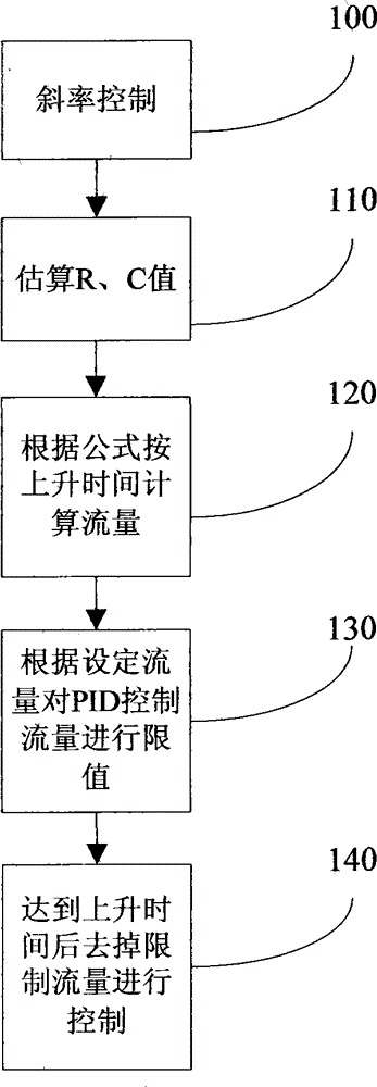
[0016] figure 1 It is a block diagram of an implementation of the present invention, wherein:

[0017] 100 Turn on the anesthesia machine and the ventilator to make them in the normal gas supply working state, and start the slope adjustment control under pressure control;

[0018] 110 Use the internal sensors of the anesthesia machine and the ventilator to estimate the R and C values ​​of the patient through the R and C rapid estimation formulas;

[0019] 120 According to the formula F=ΔP / (E*Tramp+R), calculate the maximum output control flow rate within the set rise time; where F is the average flow rate within the inhalation rise time, ΔP represents the pressure difference, E is the conductance, and Tramp is the inhalation Rise time, R is air resistance, E=1 / C, C is compliance;

[0020] 130 Set the upper limit control flow rate that is less than the set inspiratory rise time as F, and before the inspiratory rise time reaches 20% of the value of the set inspiratory rise tim...


PUM


Abstract

The invention relates to a method for controlling the inspiration ascent time of an anesthesia machine and a respirator. The method includes the following steps of: (1) estimating the air resistance (R) value and the compliance (C) value of a patient by using an R and C rapid estimation technology in a control starting state; (2) calculating an average flow rate F in an inspiration ascent time according to a formula F=Delta P / (E*Tramp+R) in an inspiration starting process; (3) setting an upper limit control flow rate in a time which is less than a set inspiration time as F in an inspiration valve and expiration valve cooperative adjustment system; (4) regularly measuring the actual flow of a feedback valve output flow rate in the inspiration ascent time, and slowly increasing the valve output flow rate to the upper limit control flow rate F when the inspiration ascent time is in the set time and the valve output flow rate is less than the upper limit control flow rate F; and (5) eliminating limitation on flow rate upper limit control of the inspiration valve and expiration valve cooperative adjustment system, and switching to inspiration valve and expiration valve cooperative pressure adjustment after the inspiration ascent time surpasses the set ascent time.

Description

technical field [0001] The present invention provides a new method for solving the slope adjustment control of the anesthesia machine and ventilator under pressure control. The inspiratory rise time is adjusted according to the preset time to adjust the slope, so that precise pressure slope control can be realized. The invention belongs to the technical field of medical equipment manufacturing. Background technique [0002] In the control of anesthesia machines and ventilators, when the inspiratory control valve and the exhalation control valve are used to work together, it is difficult to effectively adjust the inspiratory rise time because the inspiratory rise time is fixed. [0003] At present, there are two main ways to adjust the inspiratory rise time on anesthesia machines and ventilators: [0004] 1. Use the mechanical structure to adjust the flow rate of the air supply to realize the adjustment of the inhalation rise time. The advantage of this method is that the c...

Claims


Application Information

Patent Timeline
IPC IPC(8): G05B19/042A61M16/01A61M16/00
Inventor 刁俊
Owner BEIJING AEROSPACE CHANGFENG CO LTD
Learn More