
Automatic sampling device

A technology of automatic sample injection and injection valve, which is applied in measurement devices, instruments, scientific instruments, etc., can solve the problems affecting the accuracy of sample analysis and detection, long liquid flow paths, and many instruments and equipment, and achieves low cost and few instruments and equipment. , the effect of high flexibility

Active Publication Date: 2016-08-24
天津博纳艾杰尔科技有限公司
View PDF9 Cites 23 Cited by
  • Summary
  • Abstract
  • Description
  • Claims
  • Application Information

AI Technical Summary

Benefits of technology

This technology allows for quicker and more accurate testing without having to manually inject liquids into them or wait until they are ready before analyzed. It also eliminates any interference from humans that may affect their test results during this step. Additionally, there're no longer requiring an operator to handle each individual sample separately but instead only one at once. Overall, these technical features improve labor productivity while ensuring consistently reliable data quality.

Problems solved by technology

This patented technical problem addressed in this patents describes various aspects related to analyzing or detecting chemical mixtures that contain substances like solvents for example hydrocarbons (HC), amines, carboxylic acids, organic compounds, metal elements, metallurgies, plasma reactants, pesticides, environmental pollutants, drugs, biological agents, and explosives. Existing solutions involve complicated operations involving multiple components and expensive apparatus, leading to reduced reliance and efficiency while maintaining accurate measurement results over prolong periods. Therefore there is a demand for improved automation techniques capable of performing these processes without compromising their performance.

Method used


Image

  • Automatic sampling device
  • Automatic sampling device

Examples


Embodiment 1

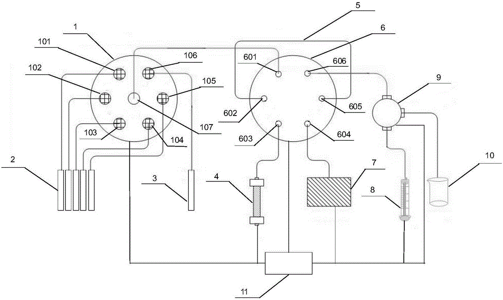
[0032] Such as figure 1 As shown, an automatic sampling device includes a channel selection valve 1, a sampling valve 6, a syringe pump 8 and an electric control mechanism 11;

[0033] The electronic control mechanism 11 single-chip interface and the channel selection valve control motor, the sampling valve control motor, through the interface and the single-chip computer online, the single-chip output signal controls the operation of the corresponding motor, and realizes the control of the channel selection valve, sampling valve and sampling pump ;

[0034] The channel selection valve 1 includes 6 input channels and 1 output channel, respectively 101-107, wherein the channels 101-105 are sample channels, which are respectively connected to the corresponding sample bottles 2, and the channel 106 is a cleaning channel, which is connected with the cleaning channel. The bottle 3 is connected, and the channel 107 is an output channel, which is connected to the sampling valve 6. T...

Embodiment 2

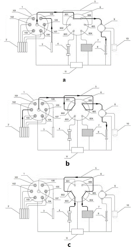
[0045] Adopt the automatic sampling device of embodiment 1 to carry out sample loading, comprise the steps:

[0046] (1) cleaning

[0047] Before sample injection, the pipeline of the sample injection system needs to be cleaned, and the quantitative loop 5 is in communication with the separation flow channel at this time. The electronic control mechanism 11 is connected to the single-chip microcomputer through the interface of the single-chip microcomputer, and controls the switching channel selection valve 1 and the channel of the sampling valve 6, wherein the channels 106 and 107 are connected, and the channels 601 and 606 are connected, and the sampling pump 8 starts the suction action, and the cleaning solution is sucked The common pipeline of the six-way sampling valve 1 is then sucked into the syringe pump 8 through the channel 601 of the six-way sampling valve through 606 through the three-way valve 9, so as to achieve the purpose of cleaning the common pipeline and the...


PUM


Abstract

The invention discloses an automatic sampling device which comprises a channel selecting valve, a sampling valve, a sampling pump and an electric control mechanism, wherein the electric control mechanism is used for controlling the channel switch of the channel selecting valve and the sampling valve and the running of the sampling pump; the automatic proceeding of the steps of liquid path cleaning, sampling and feeding of the automatic sampling device can be realized; manual sampling is not required; the influence of the manual operation on the result can be avoided; the stability, accuracy, repeatability and safety of the sampling process can be ensured; the workload of the operator can be relieved; a plurality of samples can be continuously treated; the automatic sampling device is fit for high-pass quick sampling and separating analysis of the samples in batch; instruments required by the automatic sampling device are few; the operation is simple; the cost is low; the sampling volume and sampling speed of different samples can be realized; the automatic sampling device is fit for the automatic sampling of different analysis instruments and preparing instruments, is wide in application scope and is high in flexibility.

Description


Claims


Application Information

Patent Timeline
Owner 天津博纳艾杰尔科技有限公司
Learn More