Fan

A fan assembly and body technology, applied in liquid fuel engines, non-displacement pumps, mechanical equipment, etc., can solve the problem of damage to fan assemblies

Active Publication Date: 2016-08-24
DYSON TECH LTD
View PDF10 Cites 7 Cited by
  • Summary
  • Abstract
  • Description
  • Claims
  • Application Information

AI Technical Summary

Problems solved by technology

This prevents the impeller from potentially drawing debris and dust into the fan assembly, which could damage the fan assembly

Method used


Image

  • Fan
  • Fan
  • Fan

Examples


Embodiment Construction

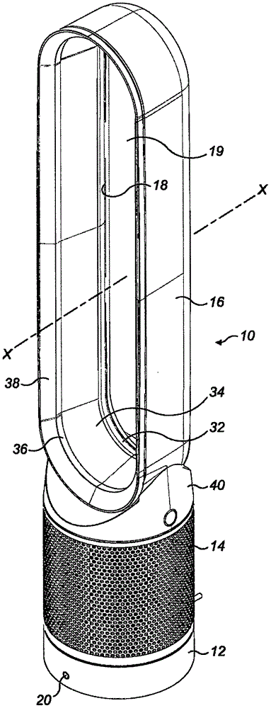
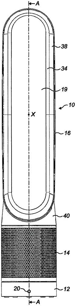
[0103] Figure 1 to Figure 3 is the external view of the fan 10, Figure 4 and 5 are shown along the figure 2 and image 3 Sectional view of the middle line A-A and B-B. exist Figure 4 As in FIG. 5 , the top of the nozzle is omitted in order to improve the clarity of the rest of the fan 10 . Generally, the fan includes a body 12 , a removable filter 14 mounted on the body 12 , and an annular nozzle 16 mounted on the body 12 . The filter 14 is placed on an annular flange 54 extending radially outwards from the body 12 , the removal of which filter from the body is prevented by the presence of the nozzle 16 . In order to remove the filter 14 from the fan 10, the nozzle 16 must first be removed.

[0104] The annular nozzle 16 has an air outlet 18 for emitting the main flow of air from the fan 10 and defines a hole 19 , or opening, through which air from outside the fan assembly 10 is drawn by the air emitted from the air outlet 18 . The body 12 further includes a user in...


PUM


Abstract

Described is a fan assembly comprising a body comprising an air inlet, an air outlet, and means for generating an air flow through the body. The fan assembly also comprises a nozzle removably mounted on the body for receiving the air flow from the body and for emitting the air flow, and a filter surrounding at least a portion of the body upstream from the air inlet, the filter being held captive on the fan assembly between the nozzle and a portion of the body while remaining free to move relative to the body and the nozzle. The filter is removable from the fan assembly only after removal of the nozzle from the body.

Description

technical field [0001] The invention relates to a fan. In particular, but not exclusively, the invention relates to a floor or table fan, such as a table fan, tower fan or floor fan. Background technique [0002] Conventional household fans typically include a set of blades or vanes mounted for rotation about an axis, and a drive for rotating the set of blades to generate an air flow. The movement and circulation of the air stream creates a "cool wind" or breeze, and as a result, the user experiences a cooling effect as heat is dissipated by convection and evaporation. The blades are typically located within a cage that allows air flow through the housing while preventing the user from coming into contact with the spinning blades during use of the fan. [0003] Document WO 2009 / 030879 describes a fan assembly that does not use blades housed in a shroud to blow air out of the fan assembly. Alternatively, the fan assembly includes a cylindrical base housing motor-driven pad...

Claims


Application Information

Patent Timeline
Patent Type & Authority Applications(China)
IPC IPC(8): F04B41/06F04D25/08F04D29/70F04F5/16F04F5/46
CPCF04D29/703F04D25/08F04D25/105F04D29/403F04D29/626F04D29/646F04F5/16F04B41/06F04F5/46
Inventor S·E·皮特J·R·金
Owner DYSON TECH LTD
Why Eureka
Try Eureka