
A steam turbine floating valve support structure

A support structure, floating technology, applied in the direction of machines/engines, mechanical equipment, engine components, etc., can solve the problems of increasing the flow loss of the airflow pipeline, reducing the steam quality, and high manufacturing costs, and achieves simple structure, advanced design, and solves the problem of installation The effect of deviation

Active Publication Date: 2017-07-28
DONGFANG TURBINE CO LTD
View PDF6 Cites 1 Cited by
  • Summary
  • Abstract
  • Description
  • Claims
  • Application Information

AI Technical Summary

Problems solved by technology

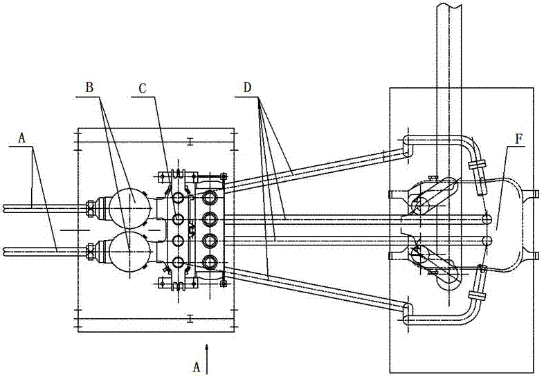
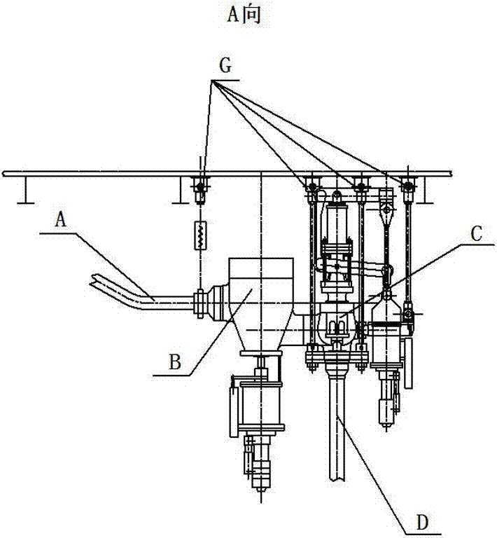
Since there is a very long pipeline between the high-pressure main steam valve B and the high-pressure cylinder F, there are several elbows from the outlet of the high-pressure main steam valve B to the inlet of the high-pressure cylinder F, which not only increases the manufacturing cost, but also increases the pipeline flow loss of the air flow. Reduced steam quality

Method used


Image

  • A steam turbine floating valve support structure
  • A steam turbine floating valve support structure
  • A steam turbine floating valve support structure

Examples


Embodiment Construction

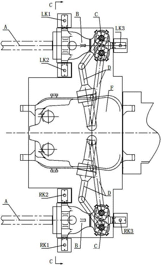
[0029] like image 3 , Figure 4 As shown, the high-pressure main steam valve B of a 350MW supercritical steam turbine unit is arranged on the operating platform on both sides of the high-pressure cylinder F, and each high-pressure main steam valve B is supported by three floating valve bracket structures of steam turbines; on the left side of the high-pressure cylinder F The high-pressure main steam valve B is supported by the left floating support structures LK1 to LK3 respectively; the high-pressure main steam valve B on the right side of the high-pressure cylinder F is supported by the right floating support structures RK1 to RK3 respectively. The total weight of the valve including valve core, insulation layer, oil motor, etc. is about 30T. After the calculation of the piping system, it is determined that the load of the 2 fulcrums of the valve support plate is 112KN, the stiffness is 1800N / mm, the thermal displacement in the direction of sky and earth is 3.5mm downward,...


PUM


Abstract

The invention discloses a steam turbine floating valve support structure, which is characterized in that it includes an adjusting screw, a valve support plate, a support rod, a sleeve, a spring cover plate, a spring bottom plate and a combined spring; The top of the valve bracket structure, its upper part is connected with the valve support plate, and its bottom is connected with the top of the strut; the strut is installed in the sleeve, and its bottom is in contact with the bottom block on the bottom of the sleeve; the upper end of the sleeve is welded on On the inner wall of the spring cover plate, the sleeve passes through the combined spring, and the bottom of the sleeve is placed in the center hole of the spring bottom plate and there is a certain gap with the spring bottom plate; the bottom of the sleeve is welded with a pad, and the bottom block is placed directly on the On the cushion block; the combined spring is located between the spring cover plate and the spring bottom plate, and tie rod bolts are arranged at the four corners of the spring bottom plate and the spring cover plate. The invention has simple structure, advanced and novel design, and effectively solves the problem of valve support arranged on both sides of the cylinder.

Description

technical field [0001] The invention relates to a steam turbine valve support device, in particular to a steam turbine floating valve support structure. Background technique [0002] As we all know, the valve is an important and indispensable part of the steam turbine system. It is not only required to quickly block the high-pressure steam under abnormal conditions, but also to adjust the intake flow of the unit according to the load demand. Therefore, the requirements for the valve housing are very high. The valve housing design At the same time, the valve has a series of valve core parts and oil motors to realize its functions. The overall valve weight is between 30T~60T. Only through the valve bracket or hanger structure can the gravity be transmitted to the equipment foundation. The valve and the cylinder are respectively connected to both ends of the pipeline. During normal operation, the valve will bear the thermal displacement and pipeline force transmitted by the pip...

Claims


Application Information

Patent Timeline
Patent Type & Authority Patents(China)
IPC IPC(8): F01D17/10
CPCF01D17/10
Inventor 袁永强杨晓燕黄果高展羽刘雄莫一波徐琼鹰曹应飞黄柳燕
Owner DONGFANG TURBINE CO LTD
Learn More